Search the Community
Showing results for 'Laser cutter'.
-
 Hi @Sam Weber and welcome to the forums, Affinity apps effectively export SVG files using 72 dpi... Other software including laser cutter software uses 96 dpi as their default which is why often you see a difference in size when importing SVG files. Depending on the laser cutter software you're using, there may (or may not) be an option in the software preferences to automatically adjust the dpi of the SVG on import... If you can let us know which laser cutter software you're using as we may be able to provide some additional options for you...
 -
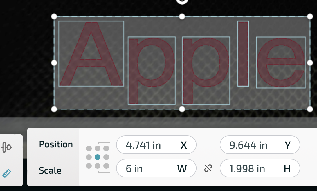
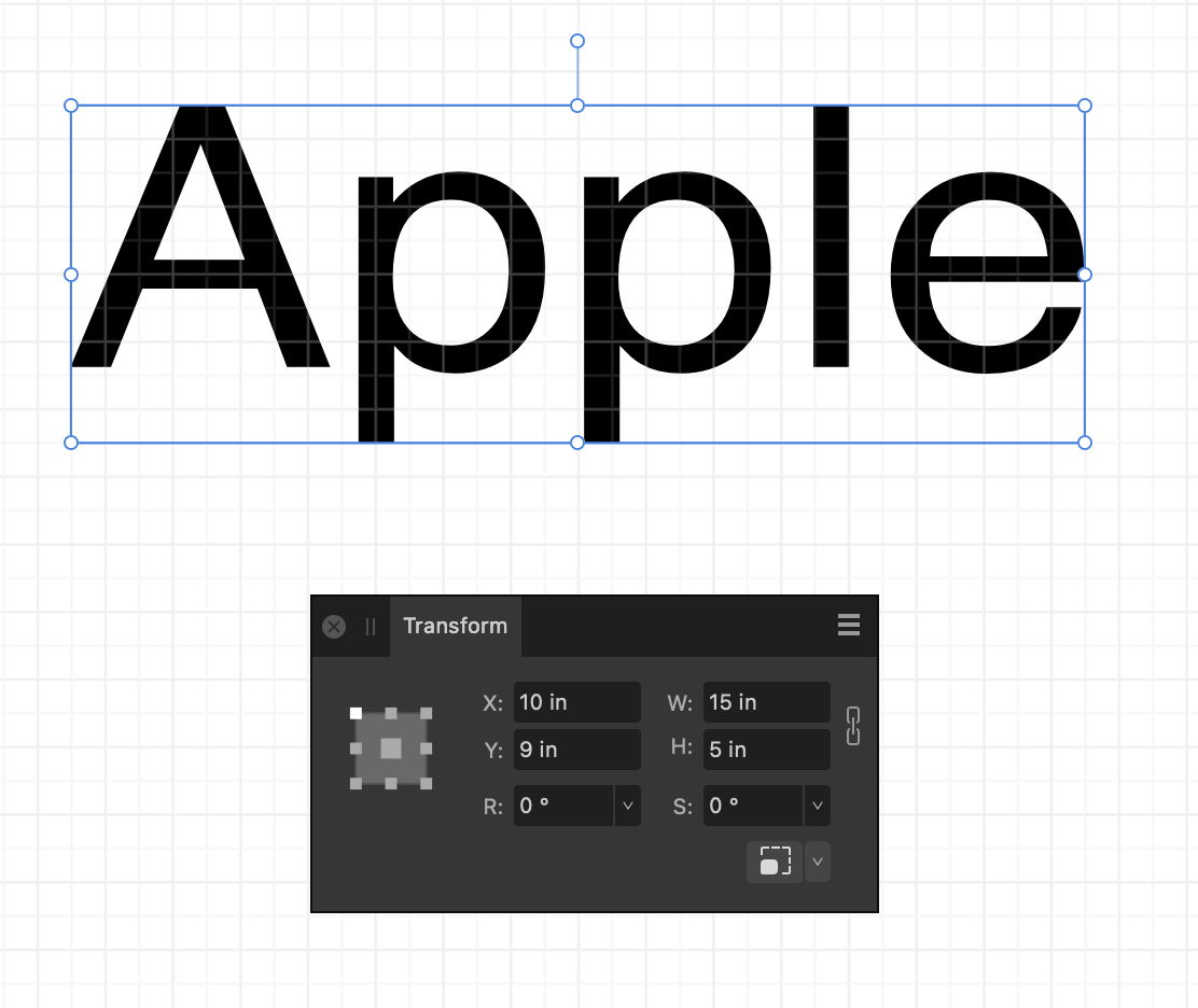
 I am trying to prepare a file to be used on a laser cutter. I am trying to simplify the paths by creating a specific colour on my design for each task for eg. Cut, Engrave, Score. The first pic is my design before attempting this. I then ungrouped all, selected same colour, black. I then went to Layer-Create compound. All of the elements in black disappeared as shown in second pic. Help, please! Either to solve why it disappeared or to recommend another route for simplifying this file for selling as an svg for laser machines. Thanks so much!
-
 Hi Via the above solution provided by hannah I slowly figured out that the box for one pixel could be directly edited to save 0.001 pt This is something that i need so as to use Afinity Designer with our laser cutter, the connection is fine and I can engrave with weights of 0.01 or above but setting the weight of the stroke to 0.001, this edit does not remain on display once the mouse moves away, only the first 0 shows. Going to be a mistake by my work place if Affinity designer can not be used as a ector drawing package with our laser cutter, hope it not true thanks Colm
 -
 I'm having the same problem -- I'm trying to export designs in SVG in order to be used by a laser cutter, and the sizes get mangled. I searched online for solutions to this and found many years of complaints and suggestions. Some of the solutions involve manually editing the SVG files in a text editor! I tried all the solutions I could find other than those, but none worked correctly in all cases. Personally, this seems strange. I would expect that keeping images the same size when exported would be the default!
 -
 Hello, I'm starting to create documents that will be used by a laser cutter and I was able to find the User Interface option to display 0.001mm in the UI. However, the lines now disappear. Is there a way to change the "display" width of strokes on the document so that the thinnest line displayed would be 1px wide? I don't mind zooming in a bit but not 20 times just to see my shapes. Thanks!
 -
 there are lots of workarounds to the better solution of having dxf output in Affinity but not very efficient for multiple projects or production use. I worked on a ranch sign for my son-in-laws ranch as a present. The laser cutting outfit only takes the design in dxf format. That seems pretty universal because their laser cutter uses dxf format. It took me a long time to reduce the polygon segments but eventually with Inkscape and Affinity Design and CanvasDraw X I got a simplified dxf file to the laser cutter. I could have paid the Laser Cutter to finish the design but was able to do it myself albeit with a lot more time and effort. This thread has been around for a long time. At some point previously someone from Affinity explained why dxf output would never happen from Affinity’s standpoint. I think with the right talent it is possible but maybe not worth the cost for Affinity.
 -
 The laser cutter we are using are machines from trumpf, a german factory. One of those lasers cost about 800.000 k up to 1 million Euro and have 6 kw power. We have 3 of them in use. One CO2 and 2 fiber laser. We laser daily steel, aluminium and stainless steel up to 25 mm thickness, over 1 million KG a year. There are other factorys that produce laser cutter in this class, like bistronic or armada, but they are all limitted to the use, finally in the operating system of the machines, to the contoll system of G-Codes. So they all need, in the end, DXF files, because its industrie standard and fits the most the norm that common CNC machines are using. We also have some 5 axis lathe machines and 3 and 5 axis milling machines. The programming system for those machines is using mostly STP files, that came out of tools like Solid Works, Solid Edge or Inventor. But finaly, the code that comes out of this system is also G-Code, with thousend of lines of code.
 -
 While I agree such a function would be desirable in theory, please take into account that Affinity misses the fundamental basics: there is no true circle object currently. You have an ellipse shape, when used as circle it has a deviation of 0,5% of radius. Affinity is a designer tool, not a school math / geometry tool / CAD tool / laser cutter tool. It does not have „objects“ or 3D capability. It uses Bézier curves instead which are approximations, perfectly suited for creative or illustrative purposes, but not suited for construction. I strongly recommend to use other tools specifically crafted to the intended use case.
 -
 Sorry but I don't understand how shape builder could perform this. I'll explain what I'm trying to do...I have a path but I want it to be be wider/larger but conform to the original shape. So I added a stroke on the original path 6 pts. So now I just want the new expanded path and not the full curve I now have. This is a path that will be sent to a laser cutter via SVG file. So I can not have anything other than the outer path.
 -

DWG and DXF Export
Sean P replied to Ash's topic in [ARCHIVE] 2.4, 2.3, 2.2 & 2.1 Features and Improvements
Looking forward to seeing the results of your exports! Curiously what software do you use to import the DXF and DWGs in? I've not done any CNC based stuff myself, but have previously used Inkscape exported DXFs with LaserCut 5.3 at our local hackspace to send to the A0 Laser Cutter. The DXFs we now export now import with LaserCut 5.3 to the correct size. -
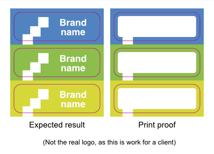
 It would never have occurred to me that this was an issue, but you're right. The tests show that importing a .afdesign file is enough to trigger the transparency warning—with PDF/X-4. It's most inconvenient, as updating images is much harder with pasted graphics, but alas. However, placing TIFFs is no problem, so placed .eps or .svg files might still work. I forgot to test that. Flyeralarm's instructions can be confusing indeed, sometimes even contradicting.* But you mentioned two interesting things here: They might use PDF/X-3 internally, and the transparency groups vanish when exporting to PDF/X-3. So, I repeated the yellow-circle test, this time with PDF/X-3 files. Lo and behold, that didn't trigger Flyeralarm's transparency warning! Therefore, I ordered the following three print proofs: 1. The document as it was, but exported as PDF/X-3. To keep this test as close to the original as possible, I deliberately left the .afdesign imports in and didn't merge the logo's elements into a single path. That is, except for one placed logo, which is a .afdesign document which has the logo merged into a path. That way, I can test two ideas at once. 2. The document rasterised to 600 ppi, except the cut contour. To be safe, I intended to export at 1200 ppi as the document contains tiny letters. However, exporting resolutions above 600 ppi in Publisher leads to another curious effect; the placed TIFF file no longer exports as a single image. Instead, Publisher exports it as 'scan lines' like an old-fashioned TV, with one image for every horizontal line. I noticed this odd behaviour in Acrobat Reader, where you can select a single line of the graphic and copy/paste it elsewhere. As I didn't feel like opening yet another can of worms, I decided to settle with a resolution of 600 ppi. 3. The document with the logos pasted in instead of imported. This test is the most interesting, as it will hopefully solve the main issue! Here's how I created the entire design: I drew these contours in Publisher. They started out as rounded rectangles (using an absolute corner radius of 3mm). They have no fill. I set the stroke to use the spot colour, with a thickness of 0.28pt and aligned to the centre (see screenshots in one of my previous replies). To make sure their laser cutter would detect all cut contours, not just one, I joined these into a single path using the Layer > Geometry > Merge Curves command. I hope that clarifies! All three proofs are in print production right now, this time hopefully with better results. Of course, I will tell you the outcome when they come in. But for now, thank you for all your help and insights, I learned a lot! * Here's a tip: switch to another language. For instance, the Dutch product information sheet for these stickers says the press-ready PDF may only contain a single (closed) cut contour, even though the image clearly shows multiple contours. However, the English information sheet gives the correct information: you can only use a single spot colour.
- 18 replies
-
- 2
-

-
- publisher v2
- (and 2 more)
-
Sorry @thomaso and @lacerto, my head was full after typing this post, so I overlooked a mistake. Here’s the correct diagram: The cut contour worked like a charm. I merged all these contours into a single path to ensure Flyeralarm’s laser cutter would find them all. That went fine, so that's not the problem. @thomaso mentioned that the white rectangle’s corner radius differs from the cut contour line radius. That is correct, and I have been looking for a stray element in my design, but it’s not there. Even in Wireframe modus, there’s nothing like it. The graphic designer at Flyeralarm also didn't find this shape in the PDF. I’m going to try your other suggestions and report back! Thank you!
-
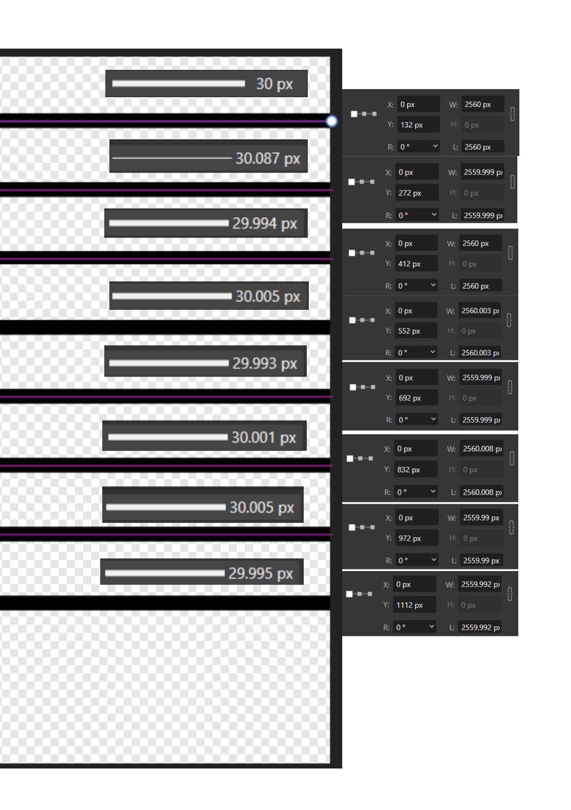
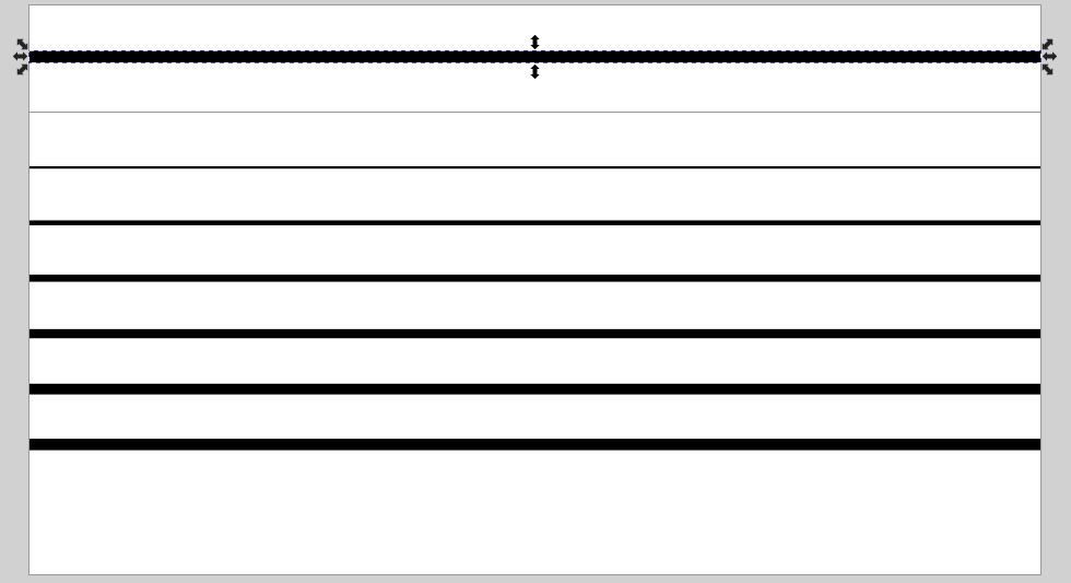
 Hi @tudor, thanks for your reply and the reply from my other post. Do you suggest this is not a bug? Even these behaviors are caused by svg limitations, Affinity should definitely handle it better. This is a design fault of the software, and design faults are also counted as bugs. SVGs are bad kids and bad kids need discipline. As long as Affinity choose to adopt them, she is responsible to discipline them, at least gets them act good in front of public. When a bad kid made troubles and got complains, his parents can't just say "My kid always gets misunderstood." but do nothing else to fix the problem. Affinity can definitely do better than this. For example, "flatten transforms" should be default for svg exports which can prevent "misunderstanding". Why?🙄Why do you ask why?🤔 Here is supposed for bug reporting right? Now you want to start a use case study session? Ok I don't mind having some laser cut file studies here. But first, when you said my setup and 1000dpi value is weird, then I suppose you have a laser cutter and prepare the files by yourself, and you know what a "normal" setup should be, right? And you, somehow, even know what machine and software I use to cut?😮(No way, just kidding😉) Only criticizing but without knowing the full picture first is not nice. Tell people "I know!" but without explaining is not constructive at all. Just like: So... Then what? You are right and I can make the same conclusion too. I just don't know how it works. For the 4 findings in my comments, you explained none of them... As long as you left the comment and likely that you know how it works, why don't you explain a little bit just like other comments above? What you said is just like "I know something you don't know but I don't bother to tell and I enjoy criticizing.", "Your file is weird. But I don't know how to improve because I don't even know your machine and your software.", "A fraction of a mm shouldn't be a roadblock to your work. Don't bother to report it! Someone else may be affected but they are not you! Just let them report it by themself!" My post is for bug reporting. Any invalid comments will just make useful findings get overlooked. Some comments may not be related to the bug but may be educational or inspirational which I find they are at least beneficial to other users reading the post. Just like all other comments above, when they pointed out something they were generous to explain and made examples. Even though they may not be helpful to the bug, at least they are beneficial to other users maybe. So, what's the purpose of your comment? Just to make yourself feel good by telling me "I know something you don't know"? Not cool.😕 Now, here's the answer to your questions and the start of laser cut files study session.🎒🏫 "my laser cutter which has A4 as its maximum project size". I know you did read it. So I feel weird that you felt weird about me using A4 to setup the project. Or did you think I made it up? 😕 Or did you think because mine is a laser cutter, so it shouldn't have the size of a printer? This logic is not quite logical.🙄 (Actually the work area is close to A4 (300x210mm). I just don't bother that 3mm.) For the 1000dpi, it's for bitmaps not for curves. For the bitmaps, they are for engraving. I engrave at 1000dpi. So, the dpi matter. It's normal for laser cutters, nothing weird here. I work on physical objects so I use physical measurements in software. My svg has both curves and bitmaps so I can send a single file to my laser cutter for both engraving the image and vector cutting the contour to finish my products. And it's neat to archive. (Actually I didn't use to prepare my files this way. It's my new method, then turns out to be less reliable. That's why I report the bug just now.) That's it! Do these make sense to you?🙂 When you have questions, you ask. When you ask, be humble and nice. This is what I deem a good attitude contributing to good conversations. 😉 Oh, one more thing. The most important one: THOSE FILES ARE JUST FOR DEMOSTRATION PURPOSE ONLY! They are work-in-progresses! I'm curious why didn't you ask me "Why do you work on color bars of 10000*10000px SVG? Are you nuts?" (Just kidding😁Of course you know they are demos) I don't worry about it. And it never gets in my way of my work at all. Actually I didn't even ask for help. I'm just doing a bug reporting. A bug is a bug. Some people, including me, report a bug not because it got in our way, it's simply because we found it, and we want to improve the software so other users won't be affected. It's for ourself and also for all users. Those fractions of mm won't have noticeable effect on my laser cut but may have negative impact on some use cases for other users, even for seasoned professional designers. Just because Affinity didn't set "flatten transforms" as default. Look at my example: Someone created a file with 8 curves here. They all look identical, 2560px long with 30px stroke. Aligned perfectly An then the file was exported as a svg and sent to me. I see something else. I see all 8 curves are not aligned with each other and the stroke are inconsistent. Then I open it with Inkscape. I see this If you receives this svg, would you feel it professional at all? "Flatten transforms" is almost always necessary. Why isn't it a default? Files here 8 lines test.svg8 lines test.afdesign Of cause we know the cause and we have workarounds. avoid resizing (inconvenient in some cases) Flatten Transforms in svg exports (if you have image layers reduced size, the canvas will still be changed in Affinity, object positions will still be shifted, possibly be fractional and get unsharp pixels. I don't know what will happen in other software.) don't use SVGs (sometimes we're forced to use, e.g. client request) I don't know if we have other workarounds. I don't even know the meaning of other options in Export Settings (e.g. Longer text span, Use tile patterns). Unfortunately no one tells me but criticizing. Anyway, it supposes to be ok. I suppose don't need to know all the options and technical details of SVG specifications. Affinity should have made us easy for exporting SVG without messing things up. Even though people "misunderstand" SVG's working principle, they deserve to get the exported files as close to their expectation as possible. A little check box "Flatten transforms" for a much better improvement. Why isn't it a default? (I really don't know and am really asking because I'm not a SVG expert) Any suggestions? 🙂
-
 I am trying to export SVG files from Affinity Designer and bring them into a range of programs for generating tabs / notches and then outputting for laser cutting. In Adobe Illustrator it is very simple - you set the document units to mm, design something with specific dimensions, and export your SVG. What comes out will be interpreted by other software, and by the laser cutter at the exact dimensions. With Affinity Designer, I've spent hours troubleshooting and digging through the forums and no matter what I do dimensions seem to vary depending on the DPI and all sorts of other options, and even slices of objects with the same height will export at different dimensions. It makes it practically impossible to predict what size your object will be. (as an aside, I thought DPI was completely irrelevant to vector - why is it even an option in a vector format?!) So is reliable scale something Affinity Designer just can't do? How are people delivering documents for print if they don't know how the printer will interpret the dimensions of their final files? I dumped Creative Cloud, bought the Affinity hoping to replace AI and now am faced with going back to Creative Cloud and getting stung with higher fees as a result of leaving. For my line of work this seems like really simple stuff...
 -
I've been using Affinity Designer to create files for use on a laser cutter and because there is no option for a hairline stroke (or near zero stroke width) I have to take my files into another program to change the stroke width before I can use the files on the laser cutter (The laser cutter views hairline or near zero stroke widths as a cut line). I love Affinity Designer but having to bring my file back and forth between different programs makes it rather frustrating. If you could please add an option for hairline or near zero stroke width (such as .001) it would make the process of designing files for laser cutting a lot less frustrating.
-
 You can thank M.C.Escher (who actually was born on June 17, the day I created this little homage). The pieces are not actually mathematically identical -- they probably were not in his original art, either (as a very productive artist, I suppose he created several versions of these lizards, a kind of Alhambra inspired mosaic). They certainly were not identical in the bitmap design that I used. I utilized vectorizer.ai to create an EPS file, and then opened that in Designer and used bitmap fill to create in one go the pieces, using this method: escher_jigsaw.mp4 I checked the Ravenburger site to learn how complex it is to create a printing punch so I do not imagine that I can ever (afford to) produce these kinds of physical puzzles myself (and just to very limited use), but I might end up producing some digital puzzles using a related concept. As I mentioned, one goal would be to produce exactly identical shapes so the idea would be offering small puzzles like above (with 31 pieces) where each piece fits, and not giving the image of the finished puzzle so part of the fun would be figuring out what the image depicts. Another goal could be producing hand-drawn puzzles with a few dozens of different real-life object-shape pieces surrounded by abstract but very irregular pieces. Designer could well be used in shape production as its vector flood tool works pretty well. EDIT: The most practical way to prepare physical tessellated pattern jigsaws (on plywood) would probably be using laser cutter to prepare multiple identical mathematically precise pieces and then hand paint them (print-time coloring might be possible, as well). Something like done here: https://www.instructables.com/End-Grain-Cutting-Board-Using-MC-Escher-Tessellati/ EDIT2: For anyone interested, it is actually possible to create these kinds of jigsaws (on plywood) using laser cutting, and it is pretty affordable. I am in the process of creating four on a single 3mm sheet each consisting of 31 pieces, with four different color images (one sided printing), and for this purpose a one-stroke-separated design is needed (vectorizer.ai can create such files, but I prepared mathematically identical pieces manually from a hexagon rather than using a raster image, but I think vectorizing from a hi-res bitmap might produce close to identical results). I falsely assumed that the cutting path needs to be routed one-way but this is not required at least by the print shop I am going to use. As for realistic puzzles, I would definitely use Blender (you could easily use Designer to create the initial "punch" wire): UPDATE: I later produced laser cut jigsaw puzzles on a 3mm plywood using both non-identical and fully identical lizard shapes in two sizes (16 puzzles per sheet and 4 puzzles per sheet) costing about EUR 100 (VAT 0) for a single 400x600mm sheet (high-res raster image printable at beam-time on single or both sides with a very little extra cost for the other side), with first-class results.
 -
 I use Affinity Designer to lay out a lot of designs which I bring over to a laser cutter. With contours now I can just do a couple test cuts, and then just select everything and adjust the whole multi-piece design to just make everything 0.015" bigger or whatever to account for the laser kerf! This is amazing and now all my stuff will fit together better and the middles of the letters won't fall out of my stencil font text as readily. I had a process for doing this before but it was awkward and destructive. This is much much better! Thank you!
 -
 I'm designing graphics to be cut with a laser cutter. I often need two copies of the same document - one horizontal and one vertical so I can pick which version fits the material on the laser cutter bed. I'm finding it hard to rotate an entire document. I can select all the object or layers and rotate that easily but the canvas does not rotate with it. I tried using an artboard created from my selection but it does not rotate with the objects either and although I can rotate the artboard, because the objects rotate about a different axis from the artboard I lose the objects off the side somewhere. I can't select both my objects and the artboard to rotate them at the same time. Next I tried copying the objects and creating a new document from the clipboard and that seems to have created it as a pixel layer because my stroke widths are now in pixels. For laser cutting it's important that the lines be a particular width or they will not cut. Help! All suggestions welcomed because I have to do this a lot.
 -
 Affinity will not export to K40 whisperer. Color is set to FF0000. I have set Affinity to factory settings. K40 whisperer can only see gray lines when exported (does not see red lines as required to cut on my CO2 laser cutter) Clearly I'm missing something here. If anyone could help with instructions/pitfalls for exporting to K40 whisperer that would be great. John
 -
Just out of curiosity - why? If it is a classic printer, not a laser cutter or a plotter, then the document will still be rasterized before printing. So isn't it better to do the conversion to the relevant DPI yourself? Or is the problem the file size, which is obviously lower with vector?
-
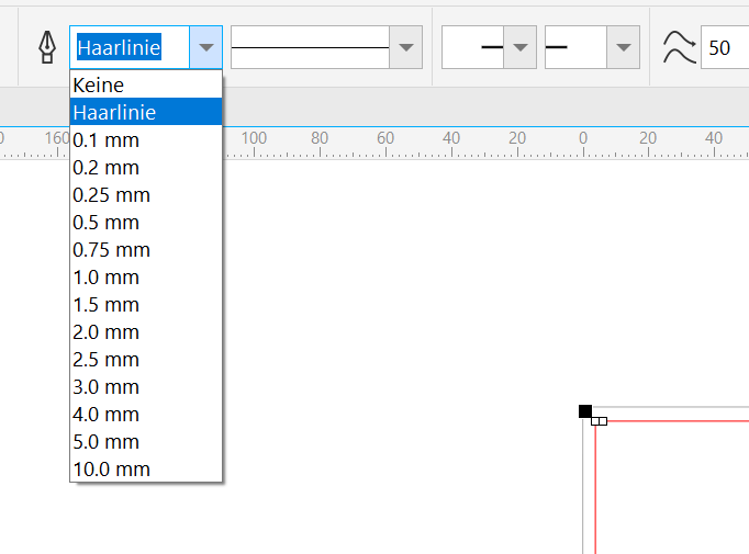
 I use the designer for making SVG files for laser cutters. Laser cutters have an internal logic to determine if a line is a cut line or an engraving line or if it's a 2D area for area engraving. Area engraving is a bit different, because the laser head is not like "follow the line", but more then "print like an ink jet printer". Obviosly cutting is not possible without a "cut line" The internal logic is determined by the thikness of the line. In other programs like Inkscape or Corel (as in this screenshot) you can choose "Haarlinie" (german for hairline) as thickness. Then and only then, a laser cutter will recognize this as a cutline. Maybe you can add the thickness "hairline" in Designer too?
- 1 reply
-
- 1
-
-
this the way I finally found to do it. i use ACD Canvas Draw X a lot so I saved in svg format from that to Inkscape Just needed dxf a couple times for a file to send to a laser cutter for a sign. You have to remember to ungroup all objects and convert to paths in Inkscape prior to saving the svg file in dxf format. Choosing Autocad R12 during the dxf saving process seemed to work best in my case but your laser cutter may want R14. Sure would like dxf format added to AD!
-
 Hi All I need to set up a template for a laser cutter and they specify that there has to be a 2mm gap between all parts. I have an oak leaf design and want to set up the file in such a way to minimise on waste. At the moment it looks like the attached. Is there a way to evenly distribute elements so that there is a 2mm gap around each object in Affinity? Or will I have to manually move stuff around - how do I check that there is a 2mm gap all the way around each element? What's the easiest way to do this is what I'm asking. Getting an error every time I try and add an image, so can't show you the template!
 -
I use SVG export in 96 dpi to ensure accuracy of dimensions reported into my laser cutter. Has worked so far with Affinity Designer. With AD 2 Beta, the SVG export does not maintain original dimensions of the vectors (comes up smaller on the laser bed)
-

export options in Designer
robboxxx replied to robboxxx's topic in Affinity on Desktop Questions (macOS and Windows)
Thank you all for the input. Being able to convert to a CAD file format is a big thing for me. Al my work is for a laser engraver/cutter. So I’m going to test those online converters. regards, rob
.png.848b6fd9797f409dd9094dcc6e1faa3b.png)
.png.23bb85f521adda13d5a9791b6cb008a0.png)