bpedit
-
Posts
227 -
Joined
-
Last visited
Recent Profile Visitors
3,062 profile views
.thumb.jpg.2ac1b0424a6896c349d3d16eea40c7f3.jpg)


-

Convert selection into a path
bpedit replied to Licorne's topic in Feedback for the V1 Affinity Suite of Products
I too need this function. Surprised it's languished so long. -
 bpedit reacted to a post in a topic:
Convert selection into a path
bpedit reacted to a post in a topic:
Convert selection into a path
-
bpedit reacted to a post in a topic:
Convert selection into a path
-
bpedit reacted to a post in a topic:
Curves not accessible from pop-up list in AP
-
When using Adjustments some functions such as Curves are not accessible from the list of options that pops up to the left of the main adjustments panel although accessible from the main panel itself. CurvesBug_1.mp4

-
bpedit reacted to a post in a topic:
Unable to edit with "Edit in Affinity Photo" An unexpected error occurred
-
The iPad model and iOS version are as in my signature above. Here's a screen recording FWIW: RPReplay_Final1736551112.MP4 Nothing can be done outside of adjustments within the color picker dialog. The app must be closed and restarted to again function. Here's a file: crashTest_1.afdesign I'm not sure if this is an expected operation, I thought maybe it was a way to insure the background was transparent in an png.
-
In iPad version 2.5.7.2948, AD crashes (locks up) when, in the Export window. I select Matte. This happens when trying to export PNG or JPEG, perhaps other formats as well. The color picker comes up and can be manipulated but there is no way to exit outside of quitting the program and re-opening. I've tried this in two separate files to the same effect.
-
nomi02118 reacted to a post in a topic:
Poster: Flash Gordon (1930s)
-
bpedit reacted to a post in a topic:
Happy Holidays!
-
And Ming! In the '50's, I couldn't wait to get home from school to see how Flash got out of the last predicament.
- 5 replies
-
- 1
-
-
- affinity designer
- affinity publisher
- (and 1 more)
-
bpedit reacted to a post in a topic:
Poster: Flash Gordon (1930s)
-
bpedit reacted to a post in a topic:
Plain cover of the German guideline for mushroom experts
-
Oufti reacted to a post in a topic:
adding Adjustments to Pixel Layers in Designer
-
Bingo! Thanks! So the solution is to paint down a base layer of white. Just tried that and it works.
-
bpedit reacted to a post in a topic:
adding Adjustments to Pixel Layers in Designer
-
bpedit reacted to a post in a topic:
adding Adjustments to Pixel Layers in Designer
-
For the following a pixel layer has been created with some practice scribbling. That layer was exported, for comparison, as a JPEG and placed back into the AD file beneath the pixel layer. The video shows a Curves adjustment and its effects (or not) on the two objects. RPReplay_Final1735166558.MP4 The file: pixelLayerAdjustmentTest.afdesign
-
I primarily work on iPad but it seems this issue is extant on Mac desktop too. I'm trying to add Adjustments to a pixel layer. This seems to work for a limited few adjustments, none useful to me. But adjustments like Levels, Curves, Contrast and most others produce no effect. If I export my pixel layer as a PNG then import it, the adjustments will work. Is there something I'm missing? The pixel layer and the imported PNG are both pixel based, it's unclear why one doesn't respond the the adjustments.
-
How about the ability to double-tap (pencil) on an item in the Layers list to add to the current non-contiguous selection? I've tried and nothing seems to happen so it seems this is available for use. Much quicker than the current method.
-
-
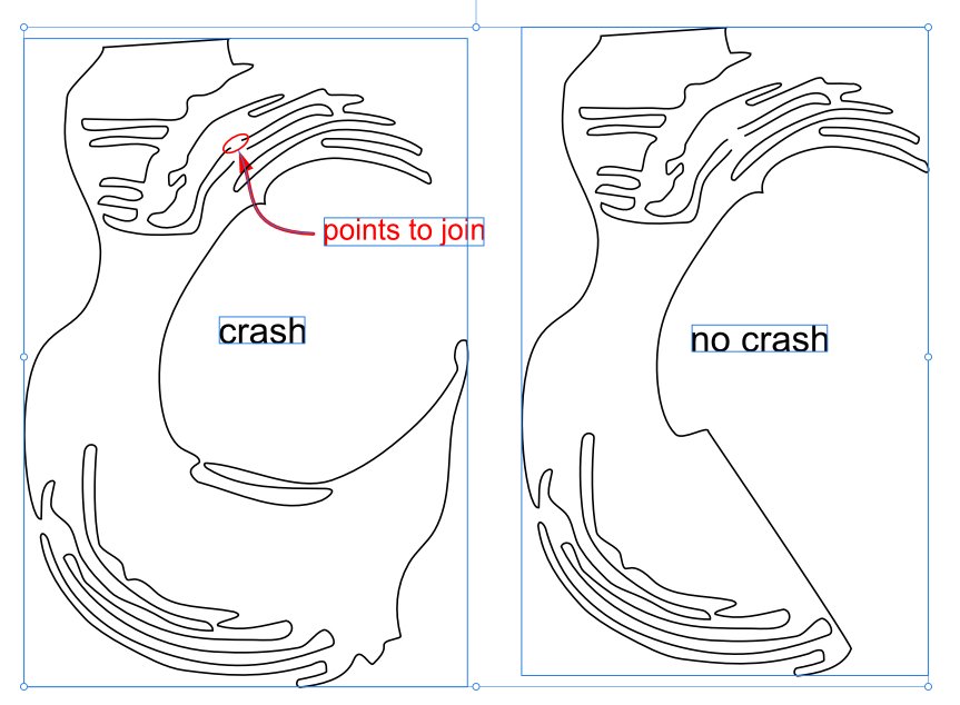
This crash is repeatable in AD 2.5.5 and extant in beta 2.6.0 as well on iPad. iMac desktop seems OK but have only tested this very small excerpt from my work. I'm on an iPad Pro, 12.9", 3rd generation running iOS 17.6.1 Two separate curves were opened and joining attempted. On the left is a simplified reduction of my curves where the issue still exists. When I simplified further to produce the curves on the right, the issue disappeared. Here is the test file: crashTest 2.afdesign
-
Yeah, I'm well aware of that but it's too cumbersome and time consuming for my use. Like trying to draw freehand with an Etch-a-Sketch. The objects I'm moving are for sizing other elements and need to be constantly repositioned and able to follow curved trajectories. But thanks.
-
Is there a way to move (translate) a very small object with the pencil without having it resize? I often have very small objects which I need to frequently reposition. They are small enough that it's nearly impossible to grab one with the pencil and not drag a corner and resize it. If I zoom in enough to accurately grab the object without selecting a corner, I can only move it a small portion of its ultimate destination due to the limited aspect. None of the added finger gestures work in this endeavor and there doesn't appear to be a way to lock size independently of translation so I'm thinking I'm out of luck but I've been surprised before.
-
bpedit reacted to a post in a topic:
Lasso selection for Designer
-
Sitaara reacted to a post in a topic:
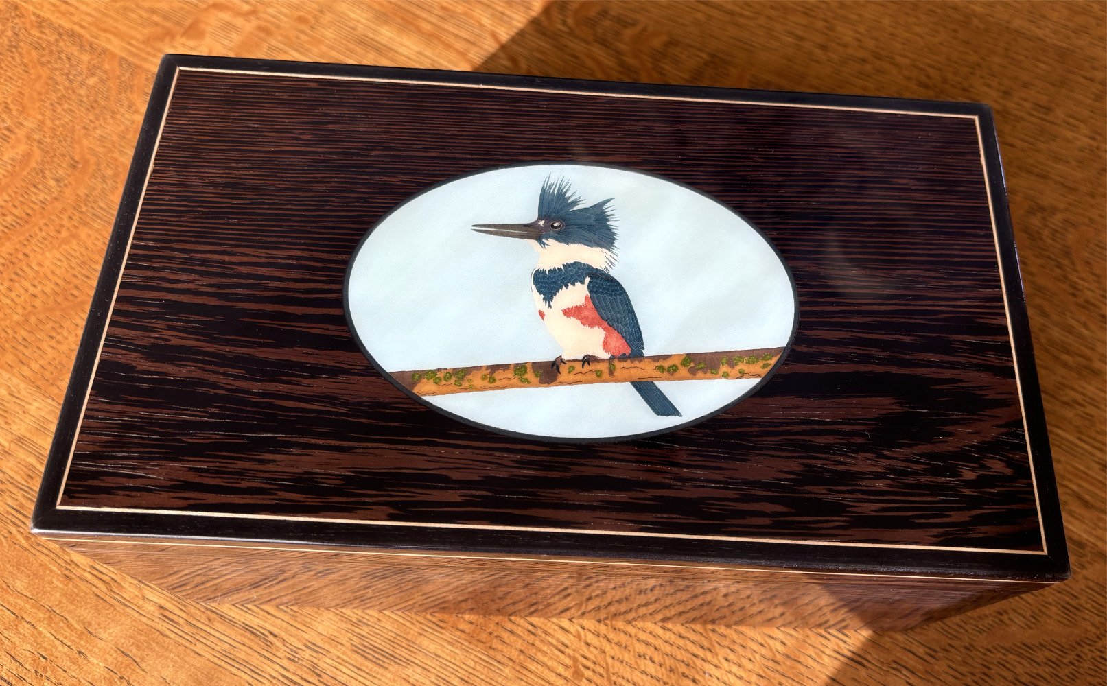
Kingfisher inlay
-
How about enabling the use of the lasso tool for objects as well as nodes (iPad). Seems like an oversight, would certainly be helpful to me, thanks.
-
StuartRc reacted to a post in a topic:
Kingfisher inlay
-
jmwellborn reacted to a post in a topic:
Kingfisher inlay
-
Ash Eldritch reacted to a post in a topic:
Kingfisher inlay
-
DelN reacted to a post in a topic:
Kingfisher inlay
-
GarryP reacted to a post in a topic:
Kingfisher inlay
-
JuN reacted to a post in a topic:
Kingfisher inlay
-
PaulEC reacted to a post in a topic:
Kingfisher inlay
-
The box is done!