Aammppaa
-
Posts
1,798 -
Joined
Posts posted by Aammppaa
-
-
Use Symbols?
Create your artwork as a Symbol, and then create your various artboards (Portrait, Landscape, Square, Small, etc) with a copy of the symbol on each.
Here's a simple example in Designer v2...
-
I know this is an old thread, but it popped up in my search results today, and piqued my interest.
On 2/9/2023 at 6:14 PM, SixSphinx said:If I move or resize one of those shapes, then everything inside the clipping shape has to be manually adjusted. I'd love to know that I'm wrong and that there's a much easier way to do this.
I can't see a way of achieving your desired result without using multiple copies of the texture and HSL adjustment.
But you can at least ensure that all the copies react to each adjustment by using Symbols (in Designer) or Linked Layers (in Photo).
They are essentially the same feature, but I personally find the interface of Linked Layers more powerful and easier to comprehend.
-
What you are asking for is a Bitmap Tracer.
Affinity does not have one, but there are plenty of others out there that you can use.
See...
I just tried https://vectorizer.ai with your image and got reasonable results, with little fiddling.
The drop shadow causes some issues as it has a soft edge, so you may wish to remove that, and reapply after the tracing.
You might also find an SVG generator that already makes Perlin noise pattern.
-
Hey @urth hooman,
Can you provide an image of the layout you want?
Also, I assume you are using Affinity Publisher v2?
-
Thanks Dan.
I was hoping to find details of which gestures are available when using graphics tablet (Wacom Intuos Pro).
I have not probed too deeply, but at the moment the pinch gesture scrolls vertically rather than zooms, and the rotation gesture is painfully slow.
But perhaps I need to look for settings in the Wacom control panel rather than Affinity?
-
Yes. Version 2 adds several new types of mask.
From the help...
Other mask types
Apart from the default mask and empty mask, Affinity Photo 2 introduces additional masking options. These are available via the Layers panel and offer more control over the edit depending on the desired workflow and outcome.
The following additional mask types are available:
- Compound Mask—a powerful masking system that uses boolean operators to combine masks non-destructively.
- Luminosity Range Mask—a live, non-destructive mask that targets pixels based on their luminosity value.
- Hue Range Mask—a live, non-destructive mask that targets pixels based on hue.
- Band-pass Mask—a live, non-destructive mask that targets pixels based on a configurable frequency band, used in a range of sharpening techniques.
-
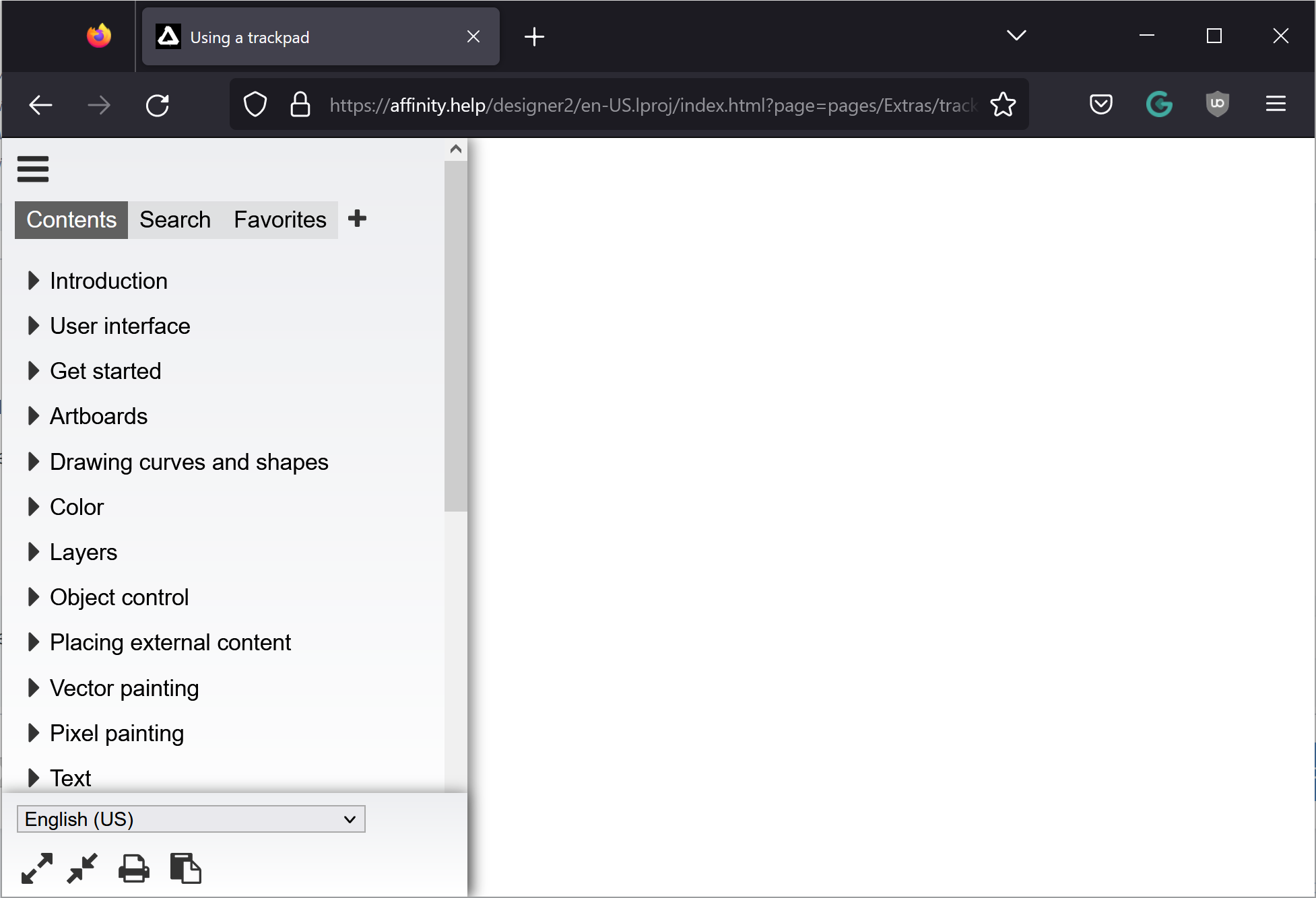
All 3 of your links give the same result... index on the left, blank page on the right.
What browser are you guy using? PC or Mac?
The information is clearly there, as you are seeing it, but I am not!
And I see the help content on all other pages that I've ever tried to look at.
-
I did exactly as you did and found the same URL.
I just followed your link on my PC in Vivaldi, Microsoft Edge, and Firefox.
In all 3 browsers I see the index on the left of the screen, and then a blank white page - no sign of the content that you show in your screenshot.

-
As I say, I am not sure I understand exactly what you are trying to achieve... but here is a file with a few variants of erase strokes, used to create a ragged border to an image or shape.
Also... why is a separate overlaid shape such a problem in your workflow? Different ragged borders could easily be stored as Assets, and then dragged over your image, snapped into place, to add any erase border you like.
-
@kirk23 perhaps I don't understand your comment... but strokes can have the Erase blend mode, which does allow for easy creation of ragged borders.
Can you show an image of what you are trying to create?
-
Hi @DaveANYC2, welcome to the forum.
Sounds like you need the Swatches panel.
You'll find a bunch of videos on YouTube that will show you various ways of using swatches...
https://www.youtube.com/results?search_query=affinity+swatches
-
Search the help for "trackpad".
Returns a page called "Using a trackpad", but there is no content.
Was hoping to find information about the gestures available when using a touch interface.
-
This post might be of help...
-
1 hour ago, myephemera said:
without having to create the individual squares and duplicate them.
You say this as if it is a bad or complicated thing?
Perhaps I am not fully understanding what you want to create, or how you intend to use it. But if all you need is a grid of squares, each of which has a different colour, then you can use the Quick Grid feature to make your array of squares in a couple of seconds.
-
I think the overcast day actually made for great images. The coloured smoke against the dark stormy sky is particularly effective.
-
Hi @Gideon S. It's generally not helpful to revive old threads - especially not those that are so ancient. Instead I'd suggest you start a new post with your own issue / query, and I'm sure you will get better help.
It would be especially helpful to include a video / screenshots of exactly what you are doing, as the basic technique of nesting an image inside a clipping shape should work every time.
Perhaps this guide helps?
-
The parallelogram shows that the gradient has been sheared / skewed / rotated from the position in which it was originally created.
This can be helpful if you have several objects that are supposed to have the same gradient (but no longer do).
If you are happy to accept the new distorted gradient, then a double click on any handle of the parallelogram will remove the additional handles.
-
Circles in Affinity are not true circles, but approximations of circles created from 4 Bezier curves. So at some rotations the 'circle' is wider / taller than at others.
I suspect that this is what we are seeing here.
Perhaps when only a single circle is selected Affinity is smart enough to know that it is supposed to be a true circle, and so lies about the true size? But when two objects are selected it can't lie about both!
EDIT: Also I notice it doesn't seem to happen with other units (I tried mm).
-
-
Hi @icetea, and welcome to the forum.
So, first suggestion... don't draw the triangle as 3 separate lines, rather as one continuous polyline, which will result in a closed curve (or shape).
See the help to find out more about Polylines.
https://affinity.help/designer2ipad/English.lproj/pages/CurvesShapes/draw_linesAndShapes.html
I'd also suggest watching a tutorial or two about using the pen tool, creating shapes, etc.
https://www.youtube.com/watch?v=XtvVEv5udVA
Secondly... a single node can only ever connect to two other nodes, so your attempt to merge the two triangles is impossible, as you'd be asking a single node to connect to four others.
Why do you need to join the nodes anyway?
If you want the two triangles to move together, just group them.
Hope these pointers help!
-
There are many solutions to this, and they all have their advantages and disadvantages. Which you choose will depend on the number of times you need to trim lines in this way, the likelyhood that you need to alter them in the future, and any other requirements (such as needing a purely vector output, or needing strokes vs shapes).
1. Expand stroke (as suggested by @R C-R)
2. Erase using Erase blend mode (suggested by @firstdefence)
3.Transparency Tool
- Use the transparency to hide the end of the stroke.
4. Clipping Shape
- Use the pen tool to draw a clipping shape...
- Start at the intersection of the two lines, and ensure you completely surround the target stroke.
- Nest the wider stroke inside the clipping shape.5. Bend the Stroke
- Change the stroke cap to Butt Cap.
- With the node tool, create a new node where the two lines first intersect.
- Remove unwanted handles with Alt + Click.
- Move the final node to bend the stroke so that the end cap is parallel to the intersecting line.6. Pixel Eraser
- Switch to Pixel persona.
- Use the Eraser to erase the end of the line. -
You need to enable Transform Mode on the toolbar of the Node Tool.
https://affinity.help/designer2/English.lproj/pages/CurvesShapes/transform_linesAndShapes.html
-
The fact that you are getting little stars suggests to me that your lines were not perfectly aligned to start with. Those tiny overlaps always existed, and were probably what is tripping up the Shape Builder.
How did you create your grid? I used a Triangle Grid, with Snap to grid enabled, and things worked well. I did get one stray line left in a resulting shape, but that was easily deleted.
Post your files if you want someone to experiment with your design.
For what it is worth, I tried out both examples, and with minimal fiddling was able to get both to work. Also I find the Illustrator example to be very inefficient, and would suggest only making ¼ of the knot, then using Symbols to fill in the other ¾ automatically.
-


Affinity was not responding on my Mac, I forced quit application, now, AFTER RESTARTING Affinity, the files I was using are now MISSING!!!
in Affinity on Desktop Questions (macOS and Windows)
Posted
Were the files saved locally (on a HD or SSD in your machine), or on network / cloud storage?