Gear maker
-
Posts
1,605 -
Joined
-
Last visited
Everything posted by Gear maker
-
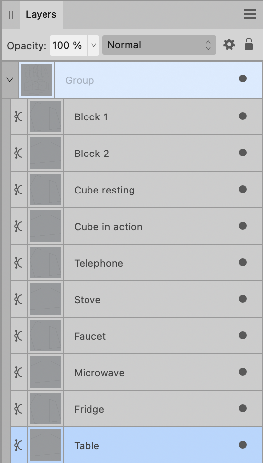
In V2 AD how can we tell if a layer is made up of a single curve or multiples? In the example below there is a mix. If I had hundreds/thousands of layers how would I be able to distinguish between a Curve and Curves? I always keep layers as a Curve unless there is a need to tie multiple layers together. So that if I click on an object in my drawing and make a change I know only that one piece will be affected. Other objects in a Curves might be way out of my view in my canvas. Also it gives me a clue that a layer is the result of a boolean operation. I guess all operations could be done as a compound so they are distinguishable.

-
V2 AD docking 3 columns of panels
Gear maker posted a topic in Desktop Questions (macOS and Windows)
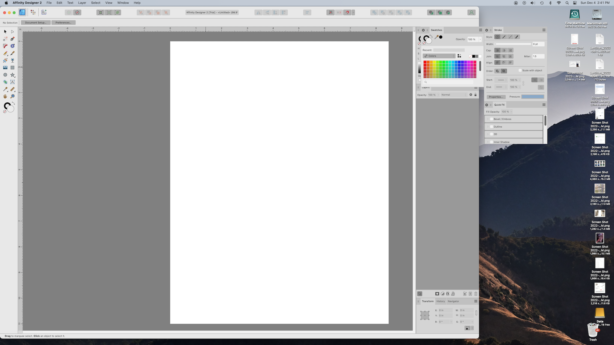
In AD V1 I'm used to using Separated Mode, which I can't in V2. But in V1 I'd have my panels spread out in 3 columns. this would allow me to change the canvas size to look at drawings/photos under AD. The panels all stayed in a known location. Like this: In V2, non-Separated mode, I have tried to create the same layout, but only the right column docks. If I change the size of the canvas to use part of my screen for viewing drawings/photos the other two columns do not move and cover the one docked column. Is there a way to dock all three columns so they all move when resizing the canvas? The two floating columns are docked together. Currently the only way I can do it, other than dragging the floating columns every time I resize the screen, is by creating multiple studio presets with the floating in various locations. Neither are very handy. Is there a trick I am missing?
-
Great. This was a major complaint I had with V2. Another was the V1 Preference setting "Auto-scroll to show selection in Layer's panel" being missing. And sure enough it looks like it's there in the hamburger menu of the Layer's panel. I haven't tested it yet but it looks good. Two birds down with one stone.
-
If I go into a complex drawing click on a few parts and do a few snips, how do I know from the layers panel that the object is made up of multiple objects? The layer name in V1 used to be showing Curves if multiple. Now it's still showing Curve. And if I have assigned a name to the object even the Curve is gone. Am I missing something in V2? Or, do I have to grab all layers in the drawing and do a separate curves? Actually if a name hasn't been assigned to the layer I find that after doing more work on the drawing, suddenly the Curve changes to Curves. Not sure what triggered it.
-
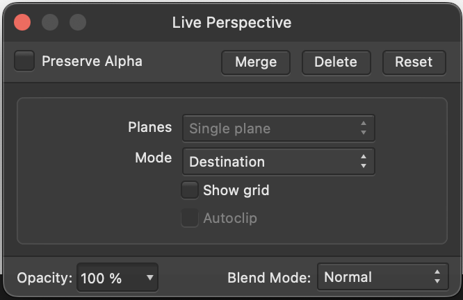
1. I created an object in a drawing I had been working on for a few hours in Designer, a circle. 2. Made it into a curve. 3. Did an Edit in Photo from the menu. 4. Selected the object I needed to change. Clicked on the symbol at the bottom of the layers panel to create a Live Filter, Perspective. 5. I didn't make any changes to the Live Perspective panel. Just moved all 4 corner nodes of my object. 6. I clicked the red exit light in the traffic signal of the Live Perspective panel. 7. Selected Edit in Designer from the menu. 8. I moved and resized the ellipse to fit in my drawing. 9. Copy and Paste object to move it to another position. 10. Observed Bounding Box stays in same location, but object has been resized and moved and rotated slightly from that of the original. If I leave out the Bold line I don't have a problem (line 10. does not happen) when I recreated this just now in a new drawing. But adding the Bold line triggered the problem. Sorry, I'm not sure what you mean about setting the Perspective filter parameters. As I mentioned above I used the default parameters in the Live Perspective filer panel. Shown below, and never changed them in AP or AD. I did find that if I didn't do line 7 and stayed in Photo I had the same results in the process. I hope that helps. In my drawing I found that having 12 circles modified by a Live perspective filter caused such a high CPU usage that for the first time in the year I've had this computer I could hear the fan running at high speed. So I used the results of the live perspective filer to create an ellipse the size and shape it gave then deleted the results. My computer was much happier with this. Thank you. Mike
-
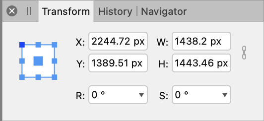
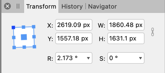
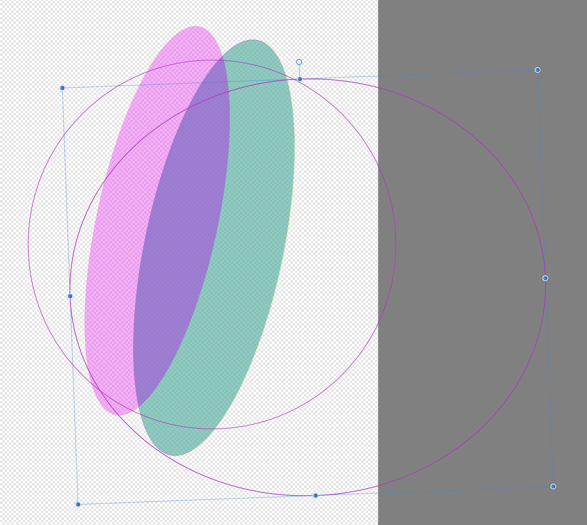
I'm not sure whether to report this as a Photo bug or a Designer bug. I found it using Designer, but it looks to come from Photo. For a drawing in Designer I needed several circles drawn in 3 point perspective. So I drew a cube in perspective then drew a circle and converted it to curves. Then chose Edit in Photo, created a live perspective of the circle so that it just fit in one face of the cube. Then moved back to Edit in Designer. I then made a copy (cmd+c and cmd+v). Much to my surprise the bounding box and image of the original circle was in the same location, but the perspective was smaller and offset considerably. I changed the color to blue just to keep track of circles. The Transform panel shows them as being in the same location. In order to get the copy to pretty much equal the original I had to make the bounding box much larger, add some angle to it and move it over. I tired it again, making the new copy purple/pink. Again the bounding box and circle's image was the same location as the layer copied, but the perspective was offset, smaller and slightly rotated. I found I got the same results in Photo. But if I created a new live perspective from a copy of the circle then the results were the same. Shouldn't each copy of a perspective be the same? Cube temp2.afdesign I'm running the latest released versions of Designer (1.10.5) and Photo (1.10.5) on a iMac (Retina 5K, 27-inch, 2020) with Monterey version 12.5. I do find that if I make multiple copies of the original they are all offset, shrunk and twisted the same.
-
Tom, the answer is most certainly yes, I would be honored. I may have even talked to you on one of our trips onboard the Minnehaha. The provenance of the Minnehaha is something right out of a Clive Cussler book. I'm glad you enjoyed the drawing as it allows me the ability to at least partially repay the enjoyment of riding the Minnehaha. I will PM you shortly with some information and we'll have to arrange to transfer the 122MB affinity file. Mike
-
Sorry you are having this problem. When I run into something like this I try increasing the Miter. I have seen that if it's not high enough the zoom will reach a place where the effect stops. So I go higher, try 30 on yours. Another thing I try to do is have a closed shape. I don't know if yours is or not, but then I can set the align to be Inside. Just thoughts for you to try.
-
Split View 2+ Documents
Gear maker replied to MoonaticDestiny's topic in Feedback for Affinity Designer V1 on Desktop
If you have in the menu Window > Separated Mode selected you can have most any combination of documents visible. -
The subtract only operates on one layer at a time. What I believe it's trying to do is to subtract the ellipse from the first line, then the first line from the second, second from the first, etc. And it hangs. Plus subtract likes to work on closed curves. Your dashes are probably open. To close these select all dashes and do an Expand Stroke. finally to get around the first issue select all dashes and do a Merge Curves. Then you will be subtracting the ellipse from the single merged layer and it should work. If you need the dashes as separate layers you can do a Separate Curves at the end to get this.
-
Troubling gradient.....
Gear maker replied to Gort's topic in Pre-V2 Archive of Desktop Questions (macOS and Windows)
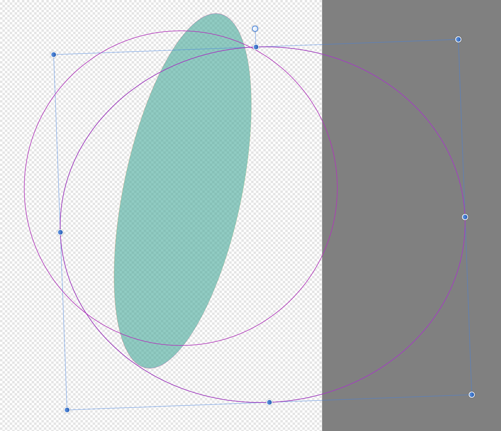
Sure, make something like this. Make sure either the black OR the white are in the exact place you want them. Then zoom in and move the two nodes close together. Move the one that's not in the exact position from above. Then when you zoom out you will have something like this.
-
Can you be more explicit? What features did you lose? It looks like you have the adjustments.
-
Won't Open File :(
Gear maker replied to SafaQ's topic in Pre-V2 Archive of Desktop Questions (macOS and Windows)
I'm just a user, and couldn't do anything with the actual file. You'll need to send it to an Affinity person. Sorry. -
Won't Open File :(
Gear maker replied to SafaQ's topic in Pre-V2 Archive of Desktop Questions (macOS and Windows)
If you copy the document to a local drive will it open? What is the size of the file? -
The Break Curve will quite simply open a node or selection of nodes. Because it has to operate on nodes it can't be used on a shape ex. rectangle, ellipse, etc. If you have an ellipse it must be converted to curves, which will result in 4 nodes. If one node is selected you will see no difference. But the curve goes from a closed curve to an open curve. If two nodes are selected you will end up with 2 curves. Either a 90 degree arc and a 270 degree arc, or two 180 degree arcs depending on the 2 nodes selected. These will be open curves that are created. If they need to be closed curves then you can select the curve and click on the Close Curve right next to the Break Curve. Of course you can add nodes anywhere they are needed and break the curve on these nodes as well as the 4 original nodes. That's really all there is to the Break Curve. I can't tell from your screen shots what you did to get the objects shown in the second and third images. I've never had it not react as expected. Maybe you can explain in more detail exactly what you are trying to do and the steps taken when it doesn't work for you. Also, which Affinity product are you working in?
-
Old Bruce, thank you. I had not taken notice of the additional line. Even though I know gradients do add this when copied. That took care of it.
-
I rarely us a conical gradient in a stroke, so I don't know if this is something only in 1.10.3 or not. Notice how in the 5:30 position there is an abrupt change in the color. The shape of this "change" changes by zooming. Test 1.afdesign There is nothing in the drawing but this one ellipse. The fill also has a conical gradient, but that doesn't seem to be causing the stroke's problem. Moving the stroke's gradient handles at 2:30, 6:00, 11:30, 10:00 and 9:30 do not have any effect, but the handle at 12:30 does affect this change. Actually the 2:30 handle does affect the issue if it's moved almost to the 6:00 position. I tried recreating the entire ellipse and the problem did not show up. Then I found that doing a Flip Horizontal corrected the issue. Also a Flip Vertical could reproduce the problem. And I had done a flip horizontal in the original drawing. It's apparently the flip that doesn't play well with the conical gradient on a stroke.
-
Setting dash/dot size in Stroke Panel
Gear maker replied to aizome's topic in Feedback for Affinity Designer V1 on Desktop
Glad I could help. Have fun. -
Setting dash/dot size in Stroke Panel
Gear maker replied to aizome's topic in Feedback for Affinity Designer V1 on Desktop
One of the issues you are running into is that you have selected a square cap which adds 1/2 the thickness of the line to the front and end of the dash. Resulting in a minimum (0) length being a square. Change it to a butt cap and you will find your 0.005 will work correctly. -
Hi Sean, sorry for the delayed response. I can't reproduce the problem. It seemed to be a 1 time occurrence. Probably just a perfect storm leading to the crash. But I figured maybe the crash report might be handy in locating some problem or another. FYI I had no symbols in this document. I use separate curves frequently, many times a day on this project. I draw the edge of something like a panel. Then duplicate it and using ctrl click remove the end two segments. Then I want to apply a lighter color stroke to the top piece and a darker to the bottom. So I have to use Separate Curves to separate the layers. And for some reason once in awhile Separate Curves won't function. After I undo back to the paste and preform the paste again it seems to always work except for this crash. Thanks for your help. Mike
-
Borders With Drop Shadows
Gear maker replied to Bart_B's topic in Pre-V2 Archive of Desktop Questions (macOS and Windows)
I'm confused, in the video you have the Gaussian Blur selected in the FX. So the blur should be changed when the slider is moved. If you select the Outer Shadow, you would have other sliders shown. Then you should be able to change the Outer Shadow. -
@SuperUserGlad it helped. Have fun. Sometimes I like doing things the hard way instead of having the software do all the work. I look to AD as being a tool box that will let me do whatever I want. Instead of wanting it to do all the work. But that could be because I am using it as a hobby instead of having to get the finished item done, NOW for business.
-
@SuperUserIt is doable but requires more manual work. I drew the design I wanted, in this case I used a grid of 0.15". Then with the pie tool I made a wedge that was 30 degrees (360 / number of segments, 12 in this case). Start angle 75 degrees and End angle 105 degrees. The wedge was resized, keeping the ratio the same, until the arc was the width as that of the bottom bar (node to node using a Butt Cap on the lines and a Miter of 2). Then in the move tool I did a cmd + J with the wedge selected. Holding cmd + shift I drug the top handle until the corners were the height of the next grid line. cmd + J then a tweak as needed to keep the to keep the corners on each grid line. Until I had 8 wedges all with the same point. Then using the node tool I moved nodes of the original design so that all vertical lines were parallel with the walls of the wedge. Then bow the horizontal lines so that they are all parallel with the rounded end of the wedges. The top horizontal lines are easier than the bottom because they are centered in the wedge. The lower ones (except on the bottom line) the right node will have to be raised to keep the line parallel with the curve of the wedge. Group the lines making up the final segment. In the Move tool turn on the Enable Transform Origin and drag the center until it snaps to the point of the wedges. Then using the Power Duplicate (cmd + J) make a duplicate. In the transform panel put in a -30 degree rotation. The 10 more Power Duplicates and it will be done. I did this fairly quickly, so it could be done better. But it gives an idea of a way to accomplish that task. Test 1.afdesign
-
I am working on a huge drawing. I created a rectangle, rotated it, converted it to a curve, then using the ctrl modifier I deleted the two ends. This resulted in a Curves of 2 lines. I did a Separate curves, but for some reason it remained a single Curves, this happens fairly often. I then clicked undo a few times backing up history to give it another try. Then it suddenly was gone. Attached is the crash report. Crash 9-15-21.txt
-
I hated this also, but in the Preferences>Tools>Use shift modifier to cycle tools will stop this. It stops the toggling of tools so hitting A more than once you will still be in the node tool. Same for all the tools. BUT there is an issue with this. The second A hit will cause designer to search out a layer with a name starting with A and if it is found then it will change layers on you. Which can be even more annoying.