kirkt
-
Posts
440 -
Joined
-
Last visited
Everything posted by kirkt
-
AP- Soft Proof - Gamut Warning with false color overlay
kirkt replied to kirkt's topic in Older Feedback & Suggestion Posts
Here is an example of the workflow in color think. kirk
-
A workflow that ultimately results in a print can benefit greatly from a color managed environment and soft-proofing for print. In pretty much every pixel editor and raw conversion application that provides soft-proofing, the gamut warning overlay is simply a single color that indicates, presumably, that those indicated pixels are out of gamut. Unfortunately, the gamut warning does not indicate how far out of gamut (in terms of dE, for example) so the warning is not very useful. It would be nice if the Soft Proof adjustment layer had a gamut warning that, when enabled, completely replaced the current working image with a false color map of the image where pixels in gamut, and up to a user-defined acceptable dE threshold (like dE=1 or 2), were green; pixels within a second user-defined dE interval were yellow (dE = 2-4) and pixels outside a third user-defined dE were red (dE > 4), or something similar. Because soft-proofing in AP is an adjustment layer, the user could pull down the opacity of this false-color map and overlay it on the original image to identify the areas on the image that fall within the most out-of-gamut regions and implement local adjustments to those areas without making global changes to areas where the issue is not such a problem. Because the rendering intent can be selected in the adjustment layer drop-down, the effect of rendering intent would be more informative by examining how the most problematic areas out of gamut get mapped toward, or into, the output gamut, instead of simply relying on the current gamut warning which is a go/no-go indicator. This approach would be really helpful in isolating specific problem areas of an image so that the user could make more informed and targeted decisions about transforming and correcting an image in a large working space, such as ProPhoto, to a smaller output space for a particular printer/paper combination. The only utility where I have seen this feature is in ColorThink, which is an application specifically intended to explore color profiles and compare images against profiles for purposes such as evaluating gamut and gamut mapping. Thank you for you consideration! Kirk Thibault Berwyn, PA
-
Of course my reply was predictable, but it looks like you got a response. I'm not sure why you think AP should have all of the tools and performance that Zerene or Helicon Focus does - it is a general purpose pixel editing application. But hey, that's one of the things that this forum is for - requesting features. Try going on the Adobe forum and posting your plea there and see what you get. Also, consider that, regardless of the tools, the Windows version of AP is months old - enhancing the features and speed of focus stacking may not be a top priority on the Windows development map. In the interim, consider using Zerene or Helicon Focus, they are both top notch. You can also use enblend/enfuse (if you do not like the command line, there are GUI's for it). Photoshop's focus stacking tools generally are not good. My standard and expectation of this forum is derived from experience with it and the software. While I do not know the developers or the forum members personally, I have found them to be helpful and I know that they are not a legion of help desk folks awaiting pleas for help 24 hours a day, but a small(er) operation trying to maintain an unrealistically high level of innovation and incorporating thousands of user suggestions, feedback and bug reports. I am impressed beyond expectation at what they have managed to accomplish in such a short period of time at what are likely unprecedented levels of growth and demand from the users. kirk
-
John Francis
kirkt replied to John Francis's topic in Pre-V2 Archive of Desktop Questions (macOS and Windows)
An example: I opened a Canon 5D IV raw file into AP (v 1.5.2) Develop persona, hit the "Develop" button and then did a Save As... to a ".afphoto" file. The raw file was converted to a 16bit file in the Develop stage. The resulting file size for the afphoto file was ~250MB for a 6744x4502 pixel RGB image. If you then export the image as a JPEG, full res, 80% quality, the resulting file is 2.4MB. This is what you should be sending to the lab for printing, unless they tell you otherwise. JPEG is an 8bit, flattened file, so you would likely save the afphoto file with all of your layers as the "master" file that you can go back to and edit, re-render to different output sizes and formats, etc. whereas the JPEG is your deliverable format. For comparison, Photoshop opens the raw image and doing a Save As... as a .psd file yields a 180MB file that is 6720 x 4480 pixels. Saving to a JPEG with level 9 out of 12 quality (about 80% of 12) yields a file that is 4.7MB. Each application is doing whatever it does, and specifying a specific compression quality in their specific JPEG engine seems to yield different results. What is sort of fascinating, and maybe someone else can try this to verify that it is not some fluke, is what happens when you start to add layers to the file. Here is the test sequence I followed. Consider opening the raw file to the background layer as "State A." Also, your file sizes may varying depending upon the pixel dimensions and the nature of the image itself, in terms of compression efficiency. State B: add a Curves adjustment layer to A, without applying any data to the inherent mask and without adjusting the curve (leave it as a straight 45 degree line). Save As... State C: stamp the layer stack (CMD+OPT+SHIFT+E or, what AP calls "Merge Visible") in B. Save As... State D: Create 3 more curves adjustment layers on top of the previous stack in C. The Curves have no mask and no adjustments made to the curve. Save As... State E: Stamp the layer stack in D. Save As... None of the curves in the above exercise actually had adjustments made to them, so the stamped pixel layers are identical to the background - more on this below. For each state, I closed the previous file, reopened StateA.afphoto, and redid all of the steps, so that the history would not accumulate, etc. Here are the resulting file sizes for each state: State File Size (MB) A 249.9 B 249.9 C 393* D 287.7 E 487 * - I redid this operation a second time and got a file size of 287.6 MB - this is what it probably should be. I redid it a third time and got 449MB. WTF? Obviously adjustment layers cost nothing in terms of file size if there is no bitmap mask associated with that layer. Add a mask and the file size increases accordingly with the number of masked layers. What is strange is the behavior of the stack and the Save As... file size when going from State B to State C to State D. Adding three curves layers onto State C (State D) dramatically decreased file size compared to C - *perhaps*. I do not get it. The fact that replicating State C three different times, all from scratch starting with a freshly opened copy of State A, produced three different results is strange. See note below. It would appear that AP is trying to optimize file size by looking at the stack and differences between various layers (pixel layers) and trying to see if they can highly compress a pixel layer that is a duplicate of another one, or something along those lines. However, it seems like whatever algorithm is being used is not very consistent in its application. It seems like adding the curves layers (State D) forced the algorithm to compress the stack properly, to get a 287MB file size. What is also interesting is the varying behaviors in States B through D if you make changes between the intervening states. If you make the Curves adjustment layers so that they stay at their default straight line (no adjustment) and stamp the stack at the previously described locations, etc., you will have a layer stack that is comprised of curves with no adjustments and stamped pixel layers that are identical to the background because the curves do nothing to alter them. If, however, you make adjustments to the curves, and the stamped pixel layers are different than the background, then the file size changes dramatically. For example, retrace the process above, but apply some arbitrary shape (an "S" curve for example) to each curves adjustment layer - call this branch of our experiment the "+" branch. Then: State File Size (MB) A 249.9 B 249.9 B+ 249.9 C 393* C+ 447.5 D 287.7 D+ 447.6 E 487.2 E+ 656 So, AP is looking at the difference in the state of the layer stack and compressing the stack dynamically based on how different pixel layers are. So, there are all probably all sorts of things going on dynamically to compress the file and save space where the operation can get away with it. However, the fact that State C above differs over three identical attempts to replicate the state is bizarre and may ultimately uncover some function of the saving algorithm that leads to bloated file sizes, perhaps unnecessarily. RAM and hard drive space is cheap, but a predictable and repeatable save algorithm is important too. kirk NOTE - It seems like some of the files that were the multiple attempts to replicate State C, versus State D, produced different stamped pixel layers (compared to the background layer), even with a curve that should have done nothing to the image. If I put the stamped pixel layer in "Difference" blend mode (comparing it to the background), there is a noticeable difference between what should be identical pixel layers. This is likely the problem with my experiment, not the save algorithm. This is still an incredibly bad problem, because it makes the file size skyrocket when the layers are even slightly (inadvertently, erroneously) different. So, an error in the stack rendering process causes large file sizes because the save algorithm sees the stamped layer as different from the background layer, even though they should be identical. Tsk tsk. Worse, it is unpredictable and not repeatable. Maybe the OP should add a blank Curves adjustment layer (or a few) to the top of his layer stack and see if it decreases his file size. Ha! -
I'm sorry that no developer has personally acknowledged and validated your frustration, but it may be time for you to move on if you truly believe what you are stating here. kirk
-
AEB to HDR Batch Processing
kirkt replied to PilotSmith69's topic in Pre-V2 Archive of Desktop Questions (macOS and Windows)
There are several HDR applications that implement batch processing. This is what you want. Photomatix, HDR Expose 3, Aurora HDR, etc. all do this - what you want will probably come down to the flexibility of the batch processor's set up options. Many of them will automatically segment your image sets based on EXIF data, but they also may give you manual control to specify X number of images per image set. In this regard, Photomatix's batch processor is most flexible. Typically the batch processor will also give you the option to specify your output, including a full 32bit HDR file (in .hdr or .exr for example) as well as a 16 or 8 bit tone mapped render based on a preset that you specify. These applications typically have trial periods, so give them a shot and see which works best for you. kirk -
So... this issue is not a "bug" but part of a much larger problem with rendering Live Filter layers in general? I tried another edit where I added a single pixel layer on top of the layer stack described above and flattened - after almost 3 minutes of churning on all cores and making the fan in my laptop work at full throttle I had to abort and kill the application. This is a real problem that will hopefully get addressed and solved - otherwise building a non-destructive workflow around Live Filters is a waste of time. Live Filter layers are basically similar to nodes in a node-based editor live Resolve, right? kirk
-
Makes sense. Kirk
-
Sweet! Nice tip @GaryLearnTech
-
I read your other posts and I agree with you assessment. Flattening a few adjustment layers on top of the two I mentioned above makes the flattening process even more measurably longer. Something with live layers needs to be optimized maybe. Kirk
-
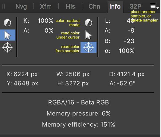
It seems like what you are trying to accomplish is to drop a color measurement target onto the image at some critical location and measure its L value. Then, with the L value measured, you want to make an adjustment (say, using Curves) to change that L value. In the video to which you linked, the author does this by using the Color Sampler Tool in PS to read the L value of a particular area of the image - he then selects this area on a Curve adjustment using the Targeted Adjustment Tool in the Curves dialog to place a point on the curve corresponding to the L value of the selected area. The author then manipulates the curve to change the L value of the area to the desired value, makes a mask to hide that adjustment layer and then selectively applies the adjustment using white paint on the layer mask to reveal the adjustment where he paints it in. This is essentially dodging and burning, setting the "exposure" adjustment with the curve and then locally and selectively applying that adjustment through the mask. You can do all of this in Affinity Photo. You can use the tools in the Info panel to make and monitor the L measurements and adjustments. You can use the Picker mode of the Curves adjustment layer to target specific areas in the image and drop a corresponding point onto the curve. You can even work in Lab in a Curves adjustment layer without changing the document's color mode to Lab. If you really need the Zone values tool, that does not exist in AP - just write down the L values that correspond to the Zones for the three color spaces that the video's author demonstrates - no need to use the panel at all, just look at your notes. Here are some Affinity tutorials that might help: Curves Picker: https://vimeo.com/154293467 Multiple Color Formats: https://vimeo.com/149265352 Here is the tutorial page (200+ videos) to browse: https://forum.affinity.serif.com/index.php?/topic/10119-official-affinity-photo-desktop-video-tutorials-200/ The Info panel is a little quirky at first - the three icons represent: top - what color mode you want the readout to display (RGB, Lab, etc.) - click on it to select the readout mode; middle - click this icon if you want the readout to display the color values under your cursor; bottom: click this icon to place a sampler and readout the color under the sampler. BE AWARE! - the sampler will be placed at the top left corner of the document - you can then drag the sampler to the desired location on the image. The top left corner is where every new sampler is created, unlike PS where the sampler gets placed on the location you click. To create more samplers, or delete existing ones, use the small flyout menu in the upper right corner of the Info panel. Like PS, there are two readouts you can configure independently. kirk
-
Hi Folks, This issue appears in both the current commercial release as well as the current beta (1.6.5 B5), so I am guessing it may just be the way it is. I have recently been experimenting with some tonal balancing operations that bring highlights down and shadows up in an image (tonal range compression). The quick and dirty description is that I start with my contrasty image and produce a grayscale from one of the channels that represents that contrast best. I make this grayscale image a new layer above the background, invert it and set it to Overlay mode. This will produce a very flat, mostly awful looking image that has lost much of its local contrast too - however, if you then apply a Gaussian blur of suitable radius to the overlay layer, local contrast is restored. In trying to devise a strategy for automation via a macro and for producing a non-destructive workflow, I have experimented with using a Gaussian blur Live Filter Layer nested in the Overlay layer with an initial radius set - the user can adjust on the fly to get a good balance of local contrast restoration without halo. Here is the rub - if all I do is set up the overlay layer with the Live Filter Layer doing the Gaussian blur and then flatten the image, it takes AP many many seconds to perform the flatten operation. If, however, I apply a Gaussian blur filter destructively to the overlay layer, the effect is nearly instantaneous - if I then perform a flatten operation, the effect is nearly instantaneous. Here is an example: 5760x3840 px Canon 5DIII image. If I use the Live Filter Layer method and nest a 100 px radius Live Filter Gaussian blur to the overlay layer, and then perform a flatten of the two layers (the Overlay layer with the live filter applied, plus the background) it takes **24 seconds** to flatten on my machine; if I perform the same, but destructive, operation of blurring the overlay layer and then flattening, each operation in that sequence is nearly instantaneous. This is on a Mac Book Pro Retina Mid 2015 model, 2.8GHz i7 4 cores, 16GB RAM, etc. OS 10.12.6. OpenGL acceleration enabled. Is there any explanation for why it appears to take AP excessively long to render the Live Filter layer when flattening? The actual drawing to screen when I adjust the Live Filter is fast, pretty much real time. Seems odd. Thanks, kirk thibault berwyn, pa usa
-
A couple of things: 1) Sort of related, at least an FYI - OCIO has been implemented as a Photoshop plug-in: http://fnordware.blogspot.com/2017/02/opencolorio-for-photoshop.html in case you want to apply a transform to a layer in PS (maybe to compare the results). It is a destructive transform though, unlike AP's implementation as an adjustment layer. 2) If you keep the OCIO adjustment layer at the top of the layer stack and turn layers below it on and off, you can see the effect that the persistent OCIO layer has on the particular layer below it that you are visualizing. However, AP does not have layer comps like PS does, so if you want to export a particular state of the layer stack, you need to do an export to a file (JPEG, TIFF, etc.) to burn the OCIO adjustment layer into the stack at its current state. Otherwise, you could create a "Macro" (AP's version of an action) to create an OCIO adjustment layer at any point in the stack you choose. Then you could group the OCIO adjustment with the particular layer and turn the whole group on and off, giving each layer that needs the OICO transform its own instance of it (at least avoiding the chance that a layer that does not need it getting it mistakenly). Unfortunately, AP does not permit grouping in a Macro, so you would have to group manually. Bummer for sure. I suppose you could create a Macro that does the following: 0) Select the layer you want to affect (i.e., transform with OCIO); 1) Run a Macro that does the following: a) create an OCIO layer above the current layer; b) select the preset transform that you want; c) select the OCIO layer and the layer you want to transform and merge the two. End. Repeat. This will burn the OCIO transform into the selected layer. This way you can apply (destructively) on a layer by layer basis the transform, skipping the layers that do not need it. Maybe? Kirk
-
Does your rendering application tag the linear output file you generate with a particular color profile? If not, then AP has no way of knowing how to interpret the color in your image, so it interprets it in the working color space (which is probably not linear). You can use an OCIO adjustment layer to tell AP how to display the image (non-destructively) so that you can work on linear data while displaying it in some other gamma encoding. The OCIO config set for vfx and animation are here: http://opencolorio.org/configurations/index.html and will probably give you the transforms you are looking for. The ACES 1.0.3 config set is particularly useful. If your image is 32bit, you can use the same transforms in the 32-bit preview panel. Unfortunately, you cannot set up AP to use a linear color space as its working color space for files lower than 32bit per channel and you cannot assign a lower bit depth (16 or 8 bit) file a linear profile. If your images are 32bit then you are good to go - just set up the color preferences properly and apply the OCIO transform you want for display in the 32bit preview panel. You can also use a LUT if you have one that does the specific transform you need, again as an adjustment layer. There are a few tutorial videos that cover processing of 3D rendering images in AP - check the video tutorials list, especially the HDR, OpenEXR and Color Management (OCIO) sections. Just a note that assigning a linear profile to the image will only change its appearance, but it will not convert the numbers to a gamma-encoded form. That is, the data remain linear but the assigning of the linear profile help with display. This is one important role that OCIO plays in AP, as an adjustment layer. Same goes for the 32-bit Preview panel. Both approaches help visualize linear data in a gamma encoded manner while maintaining the linear nature of the data for compositing, etc., where data need to add linearly to preserve light physics. It sounds like you CONVERT your linear files to sRGB in PS, which will change the data to sRGB gamma encoded numbers - are you sure this is what you want? The data are no longer linear after conversion. If that is what you want to do, you can use OCIO as an adjustment layer to do the transform and then flatten the result and assign sRGB as the color space to the document. Anyway, I hope this helps. kirk
-
Fortunately, there are plenty of raw converters out there besides LR/ACR. You may want to try Iridient Digital's X-Transformer if you are having trouble finding a good Fuji demosaic/raw converter. http://www.iridientdigital.com/products/xtransformer.html If you use a Mac, give their full-fledged raw converter a try on your Fuji files: http://www.iridientdigital.com/products/iridientdeveloper.html kirk
-
Why can I not do this?
kirkt replied to MikeFromMesa's topic in [ARCHIVE] Photo beta on macOS threads
Take your example, trying to select a rectangular window. Use the lasso tool, with SHIFT depressed, and click on each successive corner of the window area - the selection line will "connect the dots" drawing a line between each clicked point and its subsequent neighbor. When you click on the original starting point, the selection will be closed and you will get the marching ants outline of the rectangular selection area. I apologize if I am not quite understanding what you are trying to do. kirk -
Why can I not do this?
kirkt replied to MikeFromMesa's topic in [ARCHIVE] Photo beta on macOS threads
If you hold down the SHIFT key while using the freehand selection tool (the "lasso") you will constrain it to straight lines between clicks of the mouse. Remember that when you select a tool, there are helpful tool modifier hints along the bottom of the image window, including the one I just described. kirk -
Have you tried loading your equirectangular projection image (where the image is seamless, with the width equal to two times the height) and then selecting "Layer > Live Projection > Equirectangular Projection"? Tutorial videos are available in the "Live Projections" section of the tutorial videos. kirk
-
Curves are "zoomable" - you simply adjust the "Input Minimum" and "Input Maximum" to select the bounds of your curves adjustment. These values can be less than 0 and greater than 1, for unbounded 32bit images. The display of 32bit color values is not explicitly available (in an "Info" panel, for example) - however, you can open the color picker and use the color picker tool (the eyedropper) to click on a point in the image, and the color picker panel will display the intensity in the R, G and B channels in floating point format, similar to the 32bit color panel in Photoshop. kirk
-
This approach is amenable to working with with 32bit images (curve, B+W, etc. tools are all 32bit compatible) so consider using a 32bit image as source when you apply your edits. Also, when isolating a luminance range, the Curves adjustment layer permits you to specify the input range of the curve, so that the curve affects a specific portion of your unbounded 32bit data. This can be helpful in producing/avoiding clipping in the mask. kirk
-
[APh] Version 1.6 - suggested additions
kirkt replied to smadell's topic in Feedback for Affinity Photo V1 on Desktop
This is already available in v1.51. Go to Preferences -> User Interface -> Monochromatic iconography. You must restart for this change to take effect. kirk -
Cropping - am I going crazy?
kirkt replied to BkkGreg's topic in [ARCHIVE] Photo beta on macOS threads
You can also use the marquee tool to select the "crop" area/dimensions of your layer - then invert the selection (SHIFT+CMD+I) and hit delete to get rid of the pixels on that layer outside of the original selection (the inverted selection will persist until you change it or deselect). In Photoshop, for example, you can crop with a selection by making a selection and then using the Image ... Crop menu item. Here, it appears there is no "Crop" command for a selection. It may save some time to make a macro that inverts your selection, deletes and then deselects. Then you can crop with a selection in one step. It would be nice to be able to assign a keyboard shortcut to a Macro to make this kind of operation a quick keystroke. kirk -
Affinity as "plugin" in Capture One
kirkt replied to pkr1979's topic in [ARCHIVE] Photo beta on macOS threads
You will probably need to describe your workflow and color management settings in more detail for each step of the workflow. It sounds like you shoot film (black and white? color?) and then scan the negatives with an Epson scanner using the EpsonScan software. After you scan the negative, to a TIFF, what color profile tag is embedded in the file (if any)? Next, it sounds like you bring the TIFF into C1 and do various processing. Then you export the variant with your edits to AP for dust removal. What color profile tag is embedded when you export from C1 to AP? Is this the same color space that AP indicates when the file is open in AP? Then you save/save as the AP file as a TIFF and go back to C1 to do further work. What color profile tag is embedded now? Are the color space profiles that get embedded in the file color profiles or gray profiles? Do the gammas match? Review the color settings in each application that you are using to make sure that some inadvertent change is not occurring to the file that causes an application to ASSIGN a profile without your knowledge or cause the file to be displayed erroneously. kirk -
That is not constructive. Perhaps suggest some features or current limitations that you have observed, and what the devs could do to fulfill your needs. kirk
-
@terry47 - do not despair, someone has done the work for you: https://forum.affinity.serif.com/index.php?/topic/34556-affinity-photo-pdf-manual-for-your-enjoyment/ enjoy, kirk