Aammppaa
-
Posts
1,808 -
Joined
Posts posted by Aammppaa
-
-
I can't see a native way to do this.
You can work around the issue by drawing a rectangle, with snapping on so that it is the same size as the text frame, and dragging this in the layers panel to become a mask.
The mask even seems to resize correctly with the text frame - so actually quite a good method!

-
This came up before in another thread and I seem to remember that the Devs said they'd take a look to see if Text in Symbols could be improved (ie Make the attributes separate as R C-R describes above)
Similar threads…
https://forum.affinity.serif.com/index.php?/topic/29740-symbols-with-different-text-content/
https://forum.affinity.serif.com/index.php?/topic/26280-edit-text-content-in-symbols/
-
Surely symbols can be used for this in v1.5?
-
Doesn't fill all that you are requesting, but you can minimize panels vertically by double clicking the title, a further click makes them reappear.
Also you could consider adding a keyboard shortcut to open/close the various panels.
-
Then this is indeed a Windows bug.
Can a Mod move to the Bugs forum, or do we need to repost it there?
Perhaps @varnas you could change the post title to say [bug]?
-
Confirmed as described above.
Must be a bug?
-
@Alfred I know what you mean regarding optical balance, but am unconvinced that this is how alignment and snapping should work.
For one thing there is no consistency here... if optical balance is the aim, why does snapping align letter edges, and Arrange aligns bounding boxes?
Also should AD make decisions about optically aligning other objects beyond text? What if I cant to left align a circle, square and diamond? Even if they have the same areas, the difference in shape leads to very different feel for each object, but if I tell AD to left align that is exactly what it should do!
I just tried snapping in Xara Designer as a comparison, and both methods snap to the letter edge, which is what I would expect.
@R C-R if you aren't seeing the same behaviour on Mac then it could well be a bug.
-
Behaviour seems different depending on technique…
- If I write a few different words, and drag to snap the left edges, then everything aligns to the edge of the first letter as expected.
- If I use the Arrange button to align the words, this uses the bounding box, which as Varnas notes doesn't abut the letter edge, so the words end up misaligned.
This doesn't seem desirable to me.
- If I write a few different words, and drag to snap the left edges, then everything aligns to the edge of the first letter as expected.
-
This only works on Layers... in your screenshot mockup the things you've highlighted are Groups.
Create a New Layer (button bottom right of the Layers panel) and you should see the Properties on the right click / context menu.
-
I understand that this is a feature request (to allow paths to be distorted by a macro or equation), and I can see how this might be fun/useful/powerful, but for your specific case I can see a number of relatively simple workarounds.
For example...
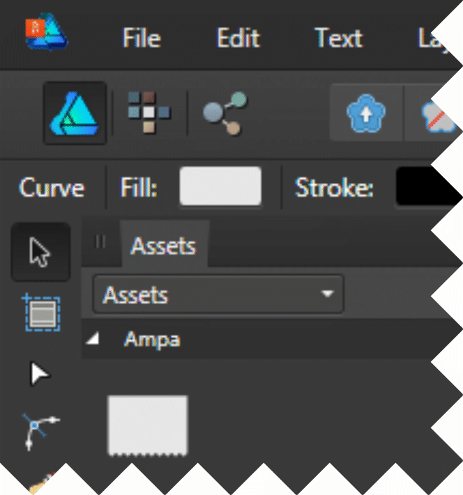
- Create a large rectangle with one side that is zigzagged.
- [Make this an Asset so that you can reuse it in future projects.]
- For any object where you want to have one or more zigzag edges, drag copies of the zigzag asset onto the object thumbnail (to make a mask layer) rotating one for each side that needs the effect.
-
Yes! Much as I like the UI I agree that there is room for improvement.
I hope that refinements such as these will be considered.
-
My first instinct was that the colour highlight is very subtle!
Just a single pixel line where I was expecting it to tint the whole folder.
Perhaps it is sufficient.
Time will tell I guess!
-
-
Have you tried recording making a Macro?
DavidDoesAffinity doesn't say whether he's using AD or AP, but I believe macros are only currently in AP aren't they, so can't be used in Designer
-
I am trying to reproduce the effect again today (PC has been shutdown since last night) and everything works as expected.
Grr... that is so annoying, because last night I played with the buggy version for half an hour trying to discover what caused the problem and it happened time and time again.
Bug occurred whether I Joined by clicking the Join button, or with the shortcut (j) which I added as Join, under both the Pen tool and Node tool.
If it happens again I'll be sure to video!
Thanks for checking.
-
OK I'll take a stab at this.
Splitting the photo into two sections...
At present there is no Cut tool in AD (it is a frequently requested feature, so will be added no doubt in the future).
However there are several ways to achieve what you are after depending on what output you want...
Vector Crop Method
- Duplicate the photo object (Ctrl+J)
- Use the Vector Crop tool to crop the top off the photo, leaving the bottom.
- Now use the Vector Crop tool to crop the bottom off the copy of the photo, leaving just the top!
Export Persona Method (if you need the sliced photo as two files for external use)
- Enter the Export Persona
- Create two slices, one for the top part of the photo, and one for the bottom.
- Export the slices!
Cutting out the Rectangle
I assume that you want to crop the photo to the rectangle, rather than end up with a photo with a rectangular hole in it.
AD excels at this task...
- In the Layers panel, just drag the rectangle on to the thumbnail of the Photo.
The rectangle is applied as a mask. This works for any shape, not just rectangles.
Finally if you've not yet read the help file (cover to cover) and watched the tutorials on the Affinity site, I strongly recommend both. They are easy to follow and cover many basic and advanced techniques.
-
-
1) I deleted the category Default form the styles panel.
Then selected an object and clicked Add Style from Selection.
I am sure that this should have been grayed out, since no category existed in which to add the Style.
AD crashed with Object Exception error.
Sadly, I have not been able to recreate this issue :(
2) With an object selected I can right click and choose Create Style, but the in the Styles panel menu Add Style from Selection is grayed out - why?
Are the two options not the same?
If they are the same, then it is confusing that one is called Create and the other Add.
- Josephmt and satamaptafe
-
 2
2
-
Odd thing just happened (AD 1.5.1.43 Win7)...
- Drew a curve
- Made a clone
- Flipped it horizontally
- Aligned the start nodes
- Attempted to join them
- And the whole lot vanishes!
I've erased the rest of the drawing leaving just the two curves, and this behaviour happens repeatedly.
File attached - try selecting the top centre nodes where the curves touch and joining.
If I tamper with the file in almost any way (such ad adding a new object to the canvas) then the curves join correctly.
What is going on?
Have just loaded the file into 1.5.0.36 Retail and the behaviour is different... here the curves remain, but do not join.
-
Agree with your observation that the feature although present is not yet developed to the same degree as it is in Photoshop.
Perhaps the devs have something to add about the issue?
-
+1 for the ability to flip about the rotation / anchor point.
Very useful to me, do it all the time in Xara Designer (or 'my old design software' as I now call it ;) ).
-
I am not familiar with Layer Comps, but they sound like what Affinity Designer calls Snapshots.
You need to enable the panel from View > Studio > Snapshots.
Then you can save Snapshots of layer states, and even export them to a new file.
-
Hilarious and very inventive.
-
Snapping with AD in a very simple case
in Pre-V2 Archive of Desktop Questions (macOS and Windows)
Posted
Snapping works on vector objects.
This is a bitmap which Designer sees only as a rectangle shape.
You can snap to the four corners or even the center with ease, but Designer will not interpret the content and allow you to snap to the corners of the flashing cursor for example.
You will either have to eyeball or use a bitmap tracer to recreate this.
Eyeballing may not be too bad, if you set up a grid of 1 pixel size, and make sure align to whole pixels is enabled, plus snap to grid.