kirkt
-
Posts
440 -
Joined
-
Last visited
Everything posted by kirkt
-
You can also put the black rectangle in place on a layer directly above the blue shape and change the blend mode of the black rectangle to "Erase." You can then group the two shapes together so you can move them as a unit, but you can still move the black rectangle relative to the blue shape (within the group) if you need to alter the knock out. Grouping will also limit the "erase" effect of the black rectangle to just the blue shape, so that the black rectangle does not erase all of the layers under the group, just the blue shape in the group. kirk
-
James' tutorial about the crop tool:
-
Bethanie
kirkt replied to bethanie's topic in Pre-V2 Archive of Desktop Questions (macOS and Windows)
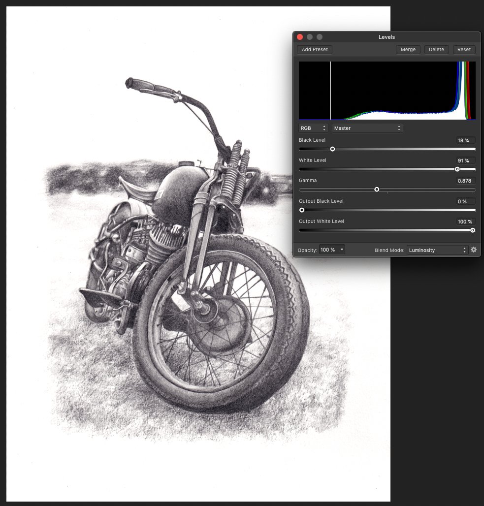
Here is a more gentle treatment of the image with gentler black and white points and some adjustment of gamma to retain the soft pencil sketch look. kirk
-
Bethanie
kirkt replied to bethanie's topic in Pre-V2 Archive of Desktop Questions (macOS and Windows)
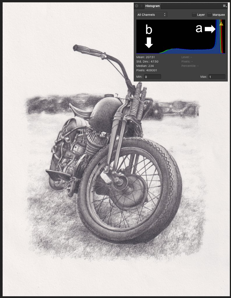
Hi @bethanie - to bring the white paper background to solid white and to add contrast to the image, you need to set your white and black points to get the effect you desire. In the first attached screenshot, take a look at the histogram of your image. The large peak on the right of the histogram at "a" is all of the near-white pixels of the paper background and its texture. The large gap at the left of the histogram at "b" is telling you that there are no pure black or near black pixels in the image. To push the near-white pixels of the paper and its texture to white, you want to set the white level of the image to an RGB value less than those pixels - this will make the near-white background completely white and remove the texture of the paper as well. It will also add contrast. To add more contrast, set the black level to something lighter than pure black - this will make the lighter black tones darker. There are several ways to do this, but the most straightforward way is with a Levels adjustment layer. In the second screenshot, I moved the white point in to 84% of pure white and moved the black point to 21% of pure black. This squeezes out the near-white pixels of the background to pure white and pushes the lighter dark tones closer to pure black. You can also use the Gamma slider to control the midtones. Take a look at the histogram of the after image -all of those near-white pixels are now clipped to pure white and the light black pixels are now near the left edge of the histogram. This is also known as histogram stretching. If the effect is too harsh and starts to bleed into the pencil shading, you can back the white and black levels off back toward their respective original values (100 and 0). Kirk
-
Does your texture image have an area of white border around it, outside of the bounds of the document? Before you try the affine transform, try right-clicking on the layer with your texture (in the Layers panel) and selecting "Rasterize and trim..." - then perform the affine transform and see if that white gap disappears. Kirk
-
Help please issue with RAW files
kirkt replied to ianhg's topic in Pre-V2 Archive of Desktop Questions (macOS and Windows)
sRAW and mRAW are pretty much relics from a time when memory cards were small and processing power of computers was not necessarily up to the task of full raw files. Nowadays, there are few, if any, compelling reasons to use it, especially given that, as the OP has discovered, few raw converters support this format. Canon's DPP produces a "correct" rendering of the OP's mRAW file because Canon supports their mRAW variation of their proprietary CR2 format. It appears that AP does not. In general, if you open a raw file (or a quasi-raw file like sRAW) and you see magenta tints where they should not be, check to see if the raw files from your camera are supported in that software. Sometimes, when you purchase a new camera and feed a raw file from it to your favorite raw converter, you might actually get the converter to produce an image even if the camera is not yet supported; however, it probably will have artifacts that should tip you off that your camera is not supported yet. Kirk EDIT: When I run your mRAW file through dcraw, the default sensor saturation level for the 7D Il is 16383, but the raw file displayed in Raw Digger shows that the green channel is clipping at 12238 in the mRAW. When I run the mRAW through dcraw with a specified sensor saturation of 12238, the magenta is almost completely gone, and the area clips to white (neutral). This is "correct" in that the mRAW is pretty much a glorified JPEG. -
Help please issue with RAW files
kirkt replied to ianhg's topic in Pre-V2 Archive of Desktop Questions (macOS and Windows)
Not all raw conversion engines fully support mRAW and sRAW - if it is really important to your AP workflow, you can always post over in the feature request section of the forum. Kirk -
Giant files after develop CR2
kirkt replied to unitizer's topic in Pre-V2 Archive of Desktop Questions (macOS and Windows)
AP is not raw converter. It is a pixel editor. The Develop module makes the raw file into an RGB file you can edit. Then export it as a JPEG. No need to save the .aphoto file. Saving a JPEG from ACR just skips the opening step. kirk -
Help please issue with RAW files
kirkt replied to ianhg's topic in Pre-V2 Archive of Desktop Questions (macOS and Windows)
I use a Mac. I do not know. sounds like the raw converter cannot reconcile the clipping properly for the quasi-raw file (ie, the mRAW is not supported). kirk -
Help please issue with RAW files
kirkt replied to ianhg's topic in Pre-V2 Archive of Desktop Questions (macOS and Windows)
Magenta highlights In clipped areas occur when the green channel clips (red+blue = magenta) and the raw converter assumes an incorrect sensor saturation value. This is a problem on the raw converter side. Try changing the raw converter used, in the Develop Assistant. kirk -
Giant files after develop CR2
kirkt replied to unitizer's topic in Pre-V2 Archive of Desktop Questions (macOS and Windows)
A 16bit per channel RGB file is that size. It has nothing to do with Affinity Photo. For example: A 6000x4000 pixel RGB image at 16 bits per channel = 6000 x 4000 pixels x 3 channels x 16 bits per channel / 8 bits per byte = 144 MB. Use 8 bit or save as a 16 bit TIFF with compression. Your raw files converted to RGB images at 16bpc have always been this big, until you save them as jpeg. Then they get automatically converted to 8bpc (jpeg is not a 16 bpc file type) and then compressed. Raw files are not images, they are a matrix of digital numbers in a pattern that gets processed into a full three-channel RGB image through a process called demosaicing. Each “pixel” in the raw file has one “channel” and is often encoded in 14 bits: 6000x4000 x 14 bits per pixel / 8 bits per byte = 42MB The raw file may actually be smaller than that if you use compressed raw, for example. kirk -
Feature Request - Alpha Channels (AGAIN!)
kirkt replied to rui_mac's topic in Feedback for Affinity Photo V1 on Desktop
You can load the spare channel (alpha) to its own pixel layer and export the AP file to a PSD. Then, in PS, copy and paste that layer into a new alpha channel in PS. This way the alpha in AP does not get premultiplied into the composite in AP and stays separate, on its own layer, for export to PS. Kirk -
Makes sense Walt. Thank you for the clarification. I’m curious, then, as to what the OP is missing when editing text. kirk
-
I think there was confusion earlier in the thread about 0 being at the center of the image. kirk
-
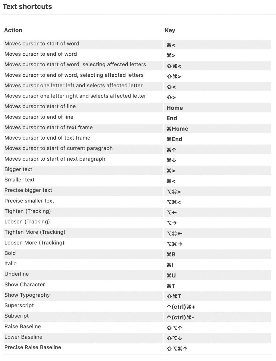
That is strange, considering the Help file for AP indicates that "⌘B" is the default keyboard shortcut for bold text. In my copy of AP, on a Mac, the "⌘B" keyboard shortcut listed in the preferences is blank as well. Perhaps the default shortcuts have been changed and the Help document is out of date. kirk
-
On1's image editor was designed relatively recently and is essentially a very slow and clunky raw converter/image editor that is a clone of Lightroom, with a bunch of "filters" to make things look nice. The fact that many of Lightroom's features, keywords and edits can be imported into the On1 environment and rendered is not surprising, seeing as how they have literally copied Lightroom's approach - the migration utility is part of their marketing On1 as a replacement for Lightroom for people who do not like Adobe's subscription model. Even if you can reverse engineer Adobe's editing pipeline, tone curves, profiles, etc., other image editors and raw converters are probably much different than Lightroom (in structure and editing controls/conversion workflow) so the "migrated conversion" may not really translate very well, or at all. Imagine migrating thousands of raw image files into a new editing environment thinking that the results of translating your previous edits will be identical to their previous conversions in the old software and then realizing you have to reconstruct thousands upon thousands of edits.... The raw file contains the data from the scene you shot, but the rendered RGB files contain your edits. Otherwise, you are depending upon the instructions from one raw converter being understood by another raw converter, which will rarely be successful. Kirk
-
Harris Shutter Effect
kirkt replied to stitch's topic in Pre-V2 Archive of Desktop Questions (macOS and Windows)
You can also do this with fewer steps using the Apply Image command and Equations. For this example, assume that you have a new document open, with the three source images layered in it. The first layer will be the image that will give us the RED channel for the Harris composite - call this layer RED. Same for the other two layers, call them GREEN (second layer) and BLUE (third layer). On the top of the layer stack, create a new pixel layer called HARRIS - make sure you fill the Alpha channel (select the HARRIS layer, then in the Channels palette, right-click on HARRIS Alpha and select "Fill" to make the Alpha channel filled with white). Now the fun begins. 1) If it is not the active layer, select the HARRIS Layer to make it active - this is going to be the layer upon which the Apply Image filter operates, so it needs to be the active layer before invoking the Apply Image command. 2) Select Filters > Apply Image... 3a) For this step, we are going to place the red channel from the RED image layer into the red channel of the HARRIS layer. To do this, drag the RED layer from the Layers palette onto the upper area in the Apply Image dialog to make the RED layer the source for the Apply Image operation. 3b) Next, check the "Equations" box and make sure the Equation Color Space is set to RGB. In the equations boxes below, you are going to specify the channels for the HARRIS layer (the "Destination" layer) based on the channels in the RED layer (the "Source" layer). In this step, we want to place the red channel from RED into the red channel of HARRIS, and leave the green and blue channels of HARRIS alone. To do this, we enter the following equations: DR = SR DG = DG DB = DB That is, the Destination Red (DR) channel (the red channel of HARRIS) equals the Source Red (SR) channel (the red channel of RED). Note that the DG = DG and DB = DB equations basically mean that the Destination Green (and Blue) equals whatever it already is (in this case, nothing). 3c) Repeat 3b for the GREEN and BLUE layers as sources for their respective channels in the HARRIS layer. So, for the green channel of the HARRIS layer, make sure HARRIS is the active layer, select Filter > Apply Image..., drag the GREEN layer onto the Apply Image dialog, check the Equations box and enter: DR = DR (leave red alone) DG = SG (place the green from the Source [GREEN] into the Destination [HARRIS]) DB = DB (leave blue alone). For the blue channel in HARRIS, drag the BLUE layer onto the Apply Image dialog - the equations will be: DR = DR DG = DG DB = SB Taa daaah! This is a more elegant method, but if you do not understand how to use Apply Image, it can be very confusing. Kirk -
Harris Shutter Effect
kirkt replied to stitch's topic in Pre-V2 Archive of Desktop Questions (macOS and Windows)
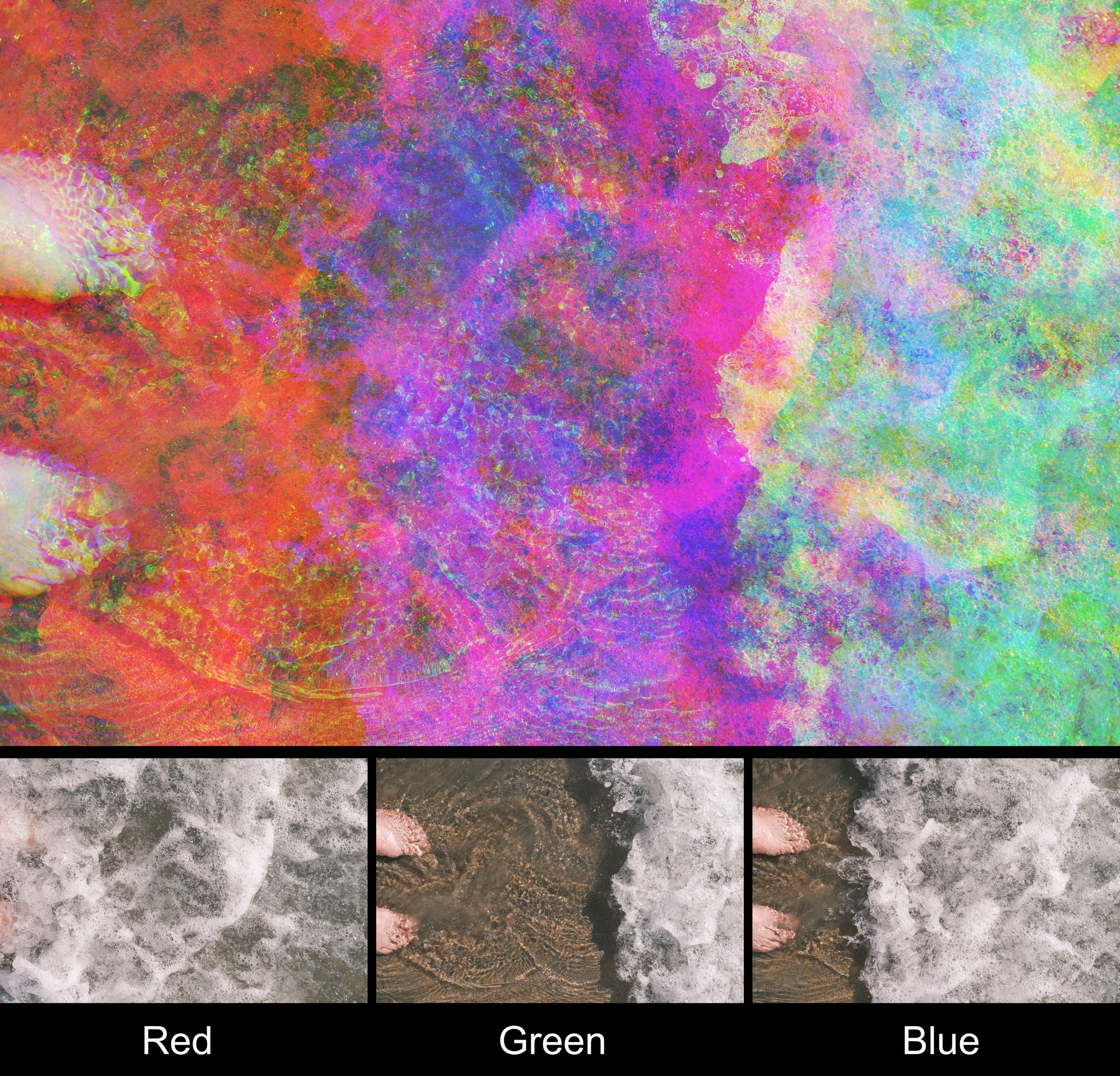
@stitch - To create the Harris Shutter effect, you need to take three images and put the red channel from the first, the green channel from the second, and the blue channel from the third into a single document. Objects in all of the images that are stationary with respect to the frame will appear as normal, full color; objects that move relative to the frame will create a rainbow-like offset effect. To do this, you can import the three images onto three layers in your working document. Then you can select the red channel from the first layer, the green channel from the second layer and the blue channel from the third layer, for example, and place them into their respective channels on a new pixel layer. This is done easily using spare channels. Create a spare channel from the RED of the first image and rename it "RED." Create a spare channel from the GREEN of the second image layer and rename it "GREEN" and create a spare channel from the BLUE channel of the third image layer and rename it "BLUE." Then, make a new pixel layer and make it the active layer in the stack - let's call this layer "Harris." Right-click on the RED spare channel and select "Load to Harris Red" - repeat for the GREEN and BLUE spare channels, selecting "Load to Harris (GREEN or BLUE). In the attached example, I took the red channel from the first image, the green channel from the second image and the blue channel from the third image and combined them as outlined above to produce the Harris Shutter result. Kirk
-
defringe worked once
kirkt replied to Riegal's topic in Pre-V2 Archive of Desktop Questions (macOS and Windows)
Also - when you are defringing something, you are really targeting a specific photographic issue that occurs at high-contrast edges of objects with optics that do not focus the spectrum of light evenly on the sensor. Find an example of fringing (chromatic aberration) and test the filter on it - you will find that it does a pretty good job. In the image you posted, there is no fringing, which may be causing some of your frustration. Kirk -
@DarkClown - If you are zoomed into 100% to view the image, then mousing on the image area to manipulate the slider gives you finer levels of control. And, when applying Unsharp Masking at such small radii, you should be making the adjustment at 100% zoom anyway, so this makes sense. That is, the incremental changes in the slider when you use your mouse to manipulate it are related to the zoom level - i.e., the pixel location on the image. This is a clever implementation of this interface feature. Perhaps in the future, a modifier key (like SHIFT) could be employed to divide the current increment by 10, to temporarily override the current zoom level increment. It sounds like the reference point for "0" is established on the image area when you first click the mouse (and then hold it to start sliding the mouse) - so pick a feature in your image that is easily identifiable and click on it to start your mousing to change the slider value. This way, you know where zero is on your image if you need to slide your mouse back toward it. Another feature that would be nice for this interface mode would be a key (something akin to TABbing through web fields) that would permit the user to step through dialog fields while mousing the field values. This way you could mouse the value for radius, then hit the TAB key, for example, and change to the Factor field, mouse the value of that, tap the TAB key again, change the Threshold field by mousing. Etc. Currently, the TAB key hides the interface, but you get the idea. Kirk
-
It looks like the image has had some cloning performed and some FFT filtration applied. DO you have the original without any of the edits applied? Kirk
-
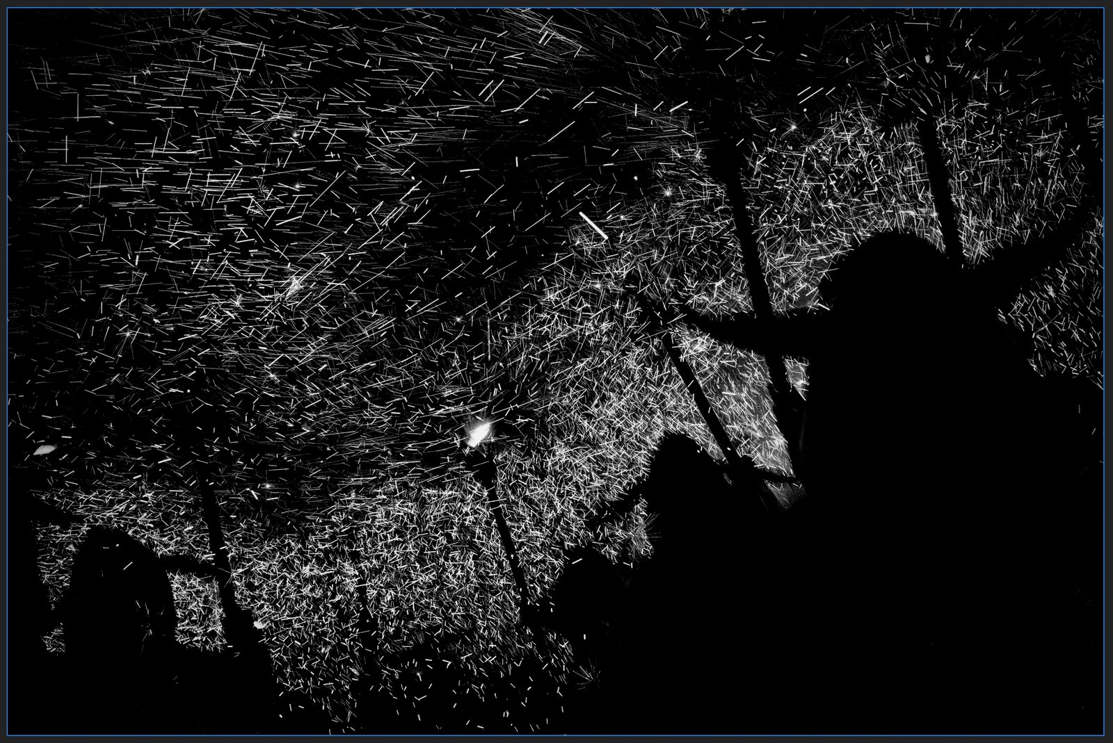
Here is the mask. kirk
-
I assume you are working with a pixel-based image (as opposed to a vector image - you mentioned "instances" but I am assuming that these are not separate objects). The sparks are the brightest parts of the image and are well-defined, so you can make a mask where the sparks are white and everything else is black. Then make a rectangle with the rectangle tool and fill it with the color you want (or a gradient, or whatever) and apply the mask. Set the blend mode of the rectangle layer to something like Linear Light. See example attached - I used a gradient. Because you use a rectangle shape (instead of filling a pixel layer) you can edit the fill once it is initially laid down, or change it to another fill type (color to a gradient, etc.). Is this what you are going for? Kirk
-
Attached is the Python code, updated to run in Python3. The code expects the file you want to transform to be named "lookup.png" kirk genc64clut.py
-
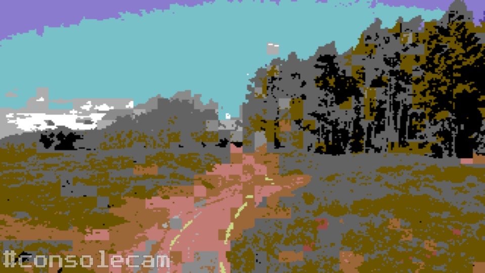
There's also an iPhone app which allows you to choose from several old consoles and computer systems from back in the day: https://apps.apple.com/us/app/consolecam/id1496896085 kirk Attached is the output of the ConsoleCam app, for the C64 hi resolution machine, with the "less detail" setting enabled.