JET_Affinity
-
Posts
532 -
Joined
-
Last visited
Everything posted by JET_Affinity
-
 Paul, It sounds like you are looking for what is usually called an "offset path" command or a "contour" command or tool for vector paths, to create paths that are offset from existing paths, but parallel to them. Does that sound right? JET
 -
Isometric Studio?
JET_Affinity replied to iamscotty's topic in Feedback for Affinity Designer V1 on Desktop
Exactly. And that's the misconception that is so pervasive nowadays; that isometric drawing is nothing more than just distorting a plan view into "30° angles" and extruding it into blocky shapes. I blame that largely on two things: The misappropriation of the "isometric" term by those creating old-style aliased computer game artwork using a 1:2 rise-to-run pixel grid (which is neither isometric nor dimetric; it's just an arbitrary oblique). The nearly complete absence of features in the vast majority of mainstream vector-based drawing programs expressly supporting axonometric drawing, ever since the advent of the "desktop revolution" in the mid-80s. The latter is an ironic and tragic pity, because: Axonometric drawing is, by definition, a 2D drawing discipline; and one every bit as venerable as the 2D converging "vanishing point" perspective still universally taught in common art classes. Axonometric drawing is applicable to all styles of commercial illustration. It is not just apropos to the purview of mechanical engineering departments. 2D axonometric drawing is no more "obsoleted" by 3D CAD than 2D "vanishing point perspective" is "obsoleted" by 3D artwork modeling programs. Mainstream Bezier-based drawing programs are 2D drawing programs used for all kinds of commercial illustration. Mainstream Bezier-based drawing programs do, in fact, provide the geometry necessary for axonometric drawing; their interface design just tends to hide it. The result is three and a half decades of neglect of one of the most important 2D drawing disciplines by most of the largest vendors of ostensibly "wide based" commercial illustration software. That's three and a half decades of software advancement and users' potential for skill-broadening fun and profit already lost. JET -
Why don't you develop the product?
JET_Affinity replied to John Mevis's topic in Feedback for Affinity Designer V1 on Desktop
And anonymous childishly insulting forum participants will be insulting. I never made apologies for being a fan of things worthy before "fanboy" became a cliché internet insult, and I still don't. So for the record: I'm an unashamed, outspoken, T-shirt wearing "fanboy" of KTM motorcycles because they're great motorcycles. That neither means I don't have my pet peeves about them, nor that I don't wish KTM would hurry up and develop what I know would be a "perfect" bike. I'm an unashamed, outspoken "fanboy" of Serif for what it's doing in plain sight with the Affinity line. That neither means I don't wish it would do some things in ways I know would be better, nor that I wouldn't love to have it all done today. The accusation of this thread was that Serif is "not developing the product." I make no apology for calling that utter nonsense. The proof is openly visible to anyone who actually bothers to investigate the progress before posting rants and insults. By the way, Affinity Dev Team, where do I get the T-shirt? (Take all the time you need. You know; 10...15 minutes.) JET -
Why don't you develop the product?
JET_Affinity replied to John Mevis's topic in Feedback for Affinity Designer V1 on Desktop
Yeah, you nod off so often, I can hear you snoring from all the way across the pond. JET -
Isometric Studio?
JET_Affinity replied to iamscotty's topic in Feedback for Affinity Designer V1 on Desktop
Iamscotty, There's no "secret" here. Many users of AI and other drawing programs have devised their own macros "("Actions" in Illustrator parlance) for doing this for many years. Examples of them are found in the user forums of the various drawing programs. Actually, skewing is unnecessary, and by understanding the underlying principles, the "rules" at play make more sense, the numbers do not seem so arbitrary, and the rationale is easier to visualize and thereby remember. As an illustrator from the days of drawing "on the board," you are surely familiar with the angle that is imprinted on every isometric ellipse template: 35°16" (35 degrees, 16 minutes). Just as with any regular drafting ellipse template, the ellipses are an orthographic projection of a circle viewed at a particular angle relative to the view's line-of-sight. In other words, the ellipse cutouts of a 25 degree drafting ellipse template are projections of a circle that is tilted 25 degrees from being viewed "edge-on." The geometry of orthographic projection dictates that the minor diameter of that ellipse is scaled by the sine of that angle. It's exactly the same with isometric ellipse templates. The minor diameter of the ellipses are scaled by the sine of 35°16". Orthographic projection also dictates that object edges perpendicular to the plane of such an ellipse (i.e., the axis which "pierces" the ellipse) is foreshortened by the cosine of the ellipse's "angle." In other words, measures along the axis about which a 25 degree ellipse "orbits" would be scaled by the cosine of 25 degrees. Again, it's the same with isometric ellipses: Measures perpendicular to the isometric ellipse are scaled by the cosine of 35°16". So to distort a 1" square into the "top" surface of an isometric view, all you need to do is: Rotate it 45 degrees. Scale it vertically 57.74% (sine of 35°, 16", expressed as a percentage rounded to two decimal places). After doing that, measure any of the sides of the path. You will find that its length is .8165 (cosine of 35°16" rounded to four decimal places). Since all three visible sides of cube in isometric orientation make the same angle with the line of sight, creating the other two sides is just a matter of rotating copies of the "top" 120° and 240°. Thus, measures along all three axes in isometric projection are foreshortened by 81.65%. All ellipses (which represent circles laying on any of the three iso planes) have minor diameters 57.74% of their major diameters. Of course these transformations work for any artwork drawn "in the flat," not just squares. Any plan view (which can include paths of any shape, text, or whatever) can be distorted into an isometric "top" view (or "floor" if you will) by those two moves. You just have to think about which direction you rotate the drawing 45 degrees, and follow the vertical scaling step by rotating either 60 degrees or -60 degrees. If the kind of drawings you do are like that (basically distorting a plan view into an isometric "floor" and then drawing verticals from that), then you can ensure correct proportion by simply multiplying your vertical height measures by .8165 (or in Affinity, keying "* sin(35.26" into the height field). But here's the thing: The whole reason for the existence of axonometric methods is to avoid all that tedium by enabling an illustrator to draw directly into the desired perspective without having to first draw multiple object sides "in the flat" and then "project" them into an auxiliary view, as is done in multi-view drafting. The reason is in the name; it's all about drawing by measuring along axes. It's not mine, either. In fact, in the 45 years or so that I've been doing axonometric drawing professionally, I've never met a fellow mechanical technical illustrator who was dependent on grids. Before computers, we used scales attached to the heads of track machines, with angular click-stops at the axes. So instead of grids, our axes (and measure origin) effectively just fluidly moved along with our hand holding the pen. I have yet to see an interface in a 2D vector drawing application that comes close to that kind of fluidity. (Certain functions of the screen overlay utility, Lazy Nezumi Pro, comes as close as I've seen.) Nonetheless, the axonometric grids feature of Affinity Designer is certainly more powerful than having to do scale, skew, rotate routines. It is well on its way toward exceeding the similar feature in much more expensive Corel Technical Designer. Moreover, we have to remember that programs like Affinity are not just for technical drawing. These are general-purpose illustration and design programs, many users of which derive a sense of "security" from page-spanning grids as they make their initial forays into isometric drawing. Fact is, isometric drawing is about much more than the relatively trivial drawing of boxy shapes extruded vertically. One doesn't engage in serious axonometric drawing long before encountering subjects which are not so conveniently boxy in shape and arranged parallel to the drawing axes or to each other. Drawing Legos is one thing. Drawing Tinker Toys is quite another. Think of an exploded parts diagram of a bicycle wheel; hub, brake caliper, spokes and nipples, chain, sprockets, rim, all in their various as-installed orientations, all to correct proportion and fit. Think of a phantom cutaway in axonometric perspective showing the inner workings of a V-twin engine. Such drawings for commercial applications are not just the domain of 3D modeling programs. Axonometric drawing is by definition a 2D drawing discipline. And it's done every day in mainstream 2D vector drawing programs, despite their usual dearth of features expressly supporting it. Off-axis object edges abound in most manufactured products. So do whole objects which are not aligned to the axes and parallel to the planes. All those measures have to be drawn in correct proportion, too, even though the drawing is done by isometric method. Fasteners, for example, are commonly positioned in all kinds of orientations in exploded isometric drawings. So providing reasonably intuitive and productive solutions for proportionally correct rotation about the axes is also of key importance. Even though its interface approach is not perfectly in line with what would be my ideal, among affordable mainstream 2D drawing programs, Affinity is presently leading the way toward (at long last) awakening more illustrators to the fun and rewarding world of axonometric drawing. And trust me, the functionality is still more direct and powerful than mere scale, skew, rotate routines. JET -
I see no reason why it wouldn't / couldn't be. If an axonometric grid is active when the Shape Tool is employed, the grid plane would correspond to the Tilt value and the perpendicular planes would correspond to the scale factor for the Extrude value. JET
-
The kind of "extrude" tools depicted in maxmax's post are not 3D modeling tools. They are straightforward 2D drawing tools. However, nor are the specific examples shown "isometric," because the original squares to which they have been applied are drawn "in-the-flat." In any axonometric orientation (of which isometric is just a special case), if the face of the extrusion were viewed "straight on", no perpendicular extrusion of that face would be visible. So those two screenshots are just arbitrary obliques. Those extrude tools can be used to help draw objects in an isometric (or other axonometric) orientation, but to do so you would first draw the shape being extruded as if it were already parallel to one of the iso planes. In other words, you would have to do other transformations and calculations in order to correctly call the result "isometric." Affinity Designer does not as yet have such an "extrusion tool." But constructing such an extrusion is fairly trivial. Just draw any shape on one of the iso grid planes, duplicate it, move it along the perpendicular axis the correctly proportional distance, use the Pen Tool in Line Mode to draw the edges of the extrusion, and delete the "hidden" edges. I quite agree that an Extrude Tool would reduce that tedium. But as always, I don't want to see Affinity merely mimic the functionally trite tools of other programs. I already have those programs. I'm frankly tired of the same old kindergarten stuff. I want to see innovatively better implementations. In this specific context, what I would envision is an enhancement to Affinity's Shape Tools. First, a little explanation: Consider that most familiar example of an "isometric" cube. The reason why the perimeter of that cube forms a hexagon is simple 2D geometry. The cube is drawn as if oriented such that the diagonal between its nearest and farthest corners is parallel to your line-of-sight. Therefore, each side of the cube makes the same angle with your line-of sight. That angle is the specific angle imprinted on every isometric drawing template: 35°16" (thirty-five degrees, sixteen minutes). Each of the three visible sides of the cube are foreshortened (scaled in one direction) by the sine of that angle. Each of the visible edges of the cube are foreshortened by the cosine of that same angle. That simple "sine and cosine" proportional principle applies not just to isometric, but to any orientation in any axonometric drawing method. The existing Shapes palette already provides a plethora of common shapes, each with special handles by which to adjust their own appropriate parameters. Corresponding numeric input fields also appear in the Control Bar for numerically specifying those parameters. Now imagine this: Suppose all of the Shape Tools simply had two additional parameters, labeled "Tilt" and "Extrude." So, for example, you use the Cog Shape Tool to draw a cog. You adjust its various parameters (inner and outer radius, number of teeth, etc.) It works as it always has for drawing a "cog" viewed "straight on." But now, in the Control Bar are the two added parameter fields. Entering an angle (or expression that yields an angle) into the Tilt field scales the shape vertically by the sine of that angle. Entering a length (or expression) into the Extrude field offsets a copy of that scaled shape and moves it vertically by the value entered multiplied by the cosine of the Tilt angle, and draws the connecting "extrusion" lines between the two. In other words, it does the same thing as those ordinary "extrude" tools in other programs, but does it in correct geometric proportion for any 3D orientation. And it does it in concert with the power of all the already existing shape-specific adjustable parameters of the Shape Tools. That's an example of adding functional elegance to a program in which a small addition compounds the functional power of existing features. That would blow the doors off any 2D Extrude Tool in any of the existing mainstream 2D drawing programs. Now imagine further that, over time, other Shape Tools were added. With the Tilt and Extrude parameters in place, imagine a Spiral Shape Tool which didn't simply "extrude" the shape along the Extrude value, but repeated the shape along the extrusion length. That could equate to a more powerful and more versatile drawing tool than the tool in Corel Technical Designer for drawing threads and threaded holes. It would be far more intuitive and less tedious than the little-known technique of using Illustrator's under-appreciated Reshape Tool for the same purposes. Imagine further that, over time, functionality were provided for something called a Shape Group; a means by which to combine two Shape Tools which could share given parameters. A Hex Bolt Shape Group would include an instance of the Hexagon Shape Tool and an instance of the Spiral Shape Tool, and the result would be the ability to instantly create correctly-proportioned hex bolts of any diameter, head size, and length—at any visual orientation. JET
-
Why don't you develop the product?
JET_Affinity replied to John Mevis's topic in Feedback for Affinity Designer V1 on Desktop
I'll second Aammppaa's response. If you actually think nothing is happening toward development of the Affinity applications, you need look no further than the Beta processes that are openly shared on this very site. This is a different world from old-school beta development programs of many monolithic software companies, in which only a select few users were privileged to know what is going on after signing a non-disclosure agreement. Go to the beta sub-forums. See the things being worked on, tested by users, and refined before release. The particular "must have" feature you have in mind may be being worked on. If not, that's what the Feature Requests sub-forum is for. Search there and find a discussion on it. The developers do review feature requests. That's where many things being developed come from. JET -
bug in transform each
JET_Affinity replied to grapher's topic in [ARCHIVE] Designer beta on Windows threads
It would be worth it. First, it would be a functional advantage over Illustrator's Transform Each dialog. There have been user requests about this and similar omissions for years on Illustrator's user forum. One of the annoying things about Illustrator is that some of its modal dialogs provide percentages, but not fixed values; others vice-versa. Some of these are obviously due to a feature being added, without updating a similar long-preexisting feature. Second, it would makes further use of Affinity's superiority in using math expressions in value fields. JET -
Pencil tool. Invisible lines.
JET_Affinity replied to Max N's topic in Feedback for Affinity Designer V1 on Desktop
Not to engage in playground bravado, but I've been making my living full-time with graphics software (primarily mainstream vector drawing programs) since its early days in the mid-80s. I may be drawing a freeform irregular shape surrounding or in relation to other objects for any of countless reasons. I may be drawing a "background" shape which I intend to send to the rear of a collection of other paths and apply a fill to it after. I may be simply drawing a path that I will compound with a pre-existing path in order to make a hole in it. I may be drawing a path to use as a clipping path. I may be drawing a path to use in a Boolean punch operation. I may be drawing a cut line for a vinyl cutter. I may be drawing in outline mode. I may be drawing a temporary construction path. OR, I may have simply switched to the Pencil tool to scribble out a path for any reason whatsoever, when the current stroke and fill just happens to be set to none or white. I still expect the tool to behave the same, by previewing the expected bitmap breadcrumb trail as I drag it. I can apply a stroke to it after mouseup, if I want to. It would be rather annoying for the program to "slap my hand" by simply refusing to preview the path I'm scribing, just because I haven't applied a stroke yet. Take a look at the corresponding tools in any of the mainstream drawing programs, Gerry. Let me put it to you this way: What is it going to hurt for the Pencil's interface to simply behave consistently, regardless of the current stroke and fill settings? I rather expect this "invisible drawing" behavior is just a bug, not a "feature." JET -
It's hard to blame it on particular authoring programs. PDFs are notorious in general for containing unexpected clipping paths, even when exported and imported using Adobe apps. As constructs native to the authoring program get "deconstructed" down to more basic objects, anything from grad fills (beyond the basic linear and radial) to mere page bounds can result in clipping paths—even multiple nested ones—when exported to PDF. It's one of the reasons why Illustrator has its specific Select>Object>Clipping Masks command. All the dubious hype about "Illustrator's native format is now PDF!" lead users to think that's true in a conventional sense. So they use Illustrator to "open" PDFs from any willy-nilly source (not just the ones created by Illustrator with its "Maintain editability..." option turned on), and encounter all those clipping paths, too. So it's common practice in Illustrator to just select that command and hit delete, in order to figure out what you're actually dealing with. JET
-
Pencil tool. Invisible lines.
JET_Affinity replied to Max N's topic in Feedback for Affinity Designer V1 on Desktop
If it were irrelevant, why would I be drawing it? You need think no further than the simple situation of intending to freehand draw a closed path. You don't think you'd want to be able to see where you started, let alone how you've weaved around and between other pre-existing objects? Sorry, Garry, but this is a no-brainer. Any freehand drawing tool should visibly trace the typical bitmap preview of the resulting path as it's being dragged. JET -
Pencil tool. Invisible lines.
JET_Affinity replied to Max N's topic in Feedback for Affinity Designer V1 on Desktop
Garry, the issue is clearly depicted in Max N's first post. He is talking about seeing the path he is drawing with the Pencil Tool being previewed even if the current fill, stroke settings are none, and he contrasts it with the {expected) preview behavior of the Bezier Pen. Again; preview of the shape you are dragging with a Pencil too—even if unpainted—is standard fare. In principle, it's the same thing as dragging with a Lasso Tool to make a freeform selection marquee. JET -
Pencil tool. Invisible lines.
JET_Affinity replied to Max N's topic in Feedback for Affinity Designer V1 on Desktop
Of course the tool should display its path as dragged, as in most every other program with a similar tool. By the same rationale, as soon as you mouseup after creating the path, it would be selected. You would expect it to be displayed so long as it is selected, regardless of whether it is painted. JET -
Bounding Box Based Transforms
JET_Affinity replied to JET_Affinity's topic in [ARCHIVE] Designer beta on Windows threads
Thanks, MEB. I'll give that a try next chance I get. I've just been running the installer with each Beta release, and leaving things as they are. I've assumed that results in a default configuration, since every time I have to turn off the dark interface. JET -
Bounding Box Based Transforms
JET_Affinity replied to JET_Affinity's topic in [ARCHIVE] Designer beta on Windows threads
Yes, I remember your mentioning that, and have been watching for it. But had figured it had slipped in priority, seeing nothing on it. I'll certainly be exploring that, now that I know it's there. JET -
Bounding Box Based Transforms
JET_Affinity replied to JET_Affinity's topic in [ARCHIVE] Designer beta on Windows threads
Well, dang! That is encouraging. Thanks for that. I was able to invoke it with the shortcut you provided, but on neither my primary desktop machine nor my Surface Pro is anything nested with the Node Tool. JET -
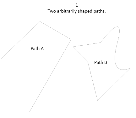
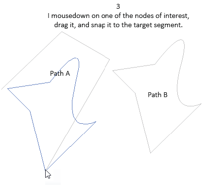
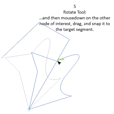
I am becoming increasingly concerned about what I consider the most debilitating aspect of Affinity Designer's drawing interface: Its dependency upon bounding boxes for all on-page transforms, especially rotations. This is downright amateurish in comparison to tools-based transforms. The functionality depicted below is from Illustrator. The same thing can be done in Corel Draw. It's a procedure I use everyday, all-day. The exact use case could be anything. Be it a loosey-goosey cartoon, a portrait, a product label, a photo-realistic drawing of a motorcycle, or anything in between, the argument is valid for any kind of serious illustration work: In most cases, bounding box handles simply do not correspond to the details of interest when performing snap-sensing on-page transforms directly and intuitively with the mouse. Related concerns: Like Illustrator and all the other programs that copy-cat it, Affinity Designer has modeled its interface upon the despised, but now conventional wisdom, "necessity" for two separate and distinct primary selection tools. (Despised, that is, by me and many others who remember the functionally superior single selection tool of FreeHand.) But even accepting that as a battle lost, these concerns make matters even worse in Affinity: Selection: A path selected by the black pointer is selected as a whole; i.e., it is selected at the object level. Per conventional treatment, doubleClicking is the shortest shortcut to putting the path in "edit mode." So here's the issue: By what logic does doubleClicking the path to put it in "edit mode" effectively deselect all of its nodes? Of what use is that selection state? The program should not assume that I want to manipulate a sub-set of the nodes, especially given that I cannot even use the black pointer to drag a path by one of its nodes, as I can in other programs that let me turn off the infernal, visually cluttering, omnipresent bounding boxes. A selected path is selected as a whole. DoubleClicking it should therefore initially have all of its nodes selected, not none of them. That way, it is at least ready for the user to simply mousedown on a particular node to drag the whole path by that node, and snap it to any snapping candidate within pick distance. Pen Tool: Turn on Line Mode. Draw a diagonal path. Now tell me: What is the length of that path? At what angle was it drawn? With the bounding box failing the job, knowing that, I could at least use the Transform panel to rotate something else to that exact angle? But about that other object: How can I determine the present angle of the portion of it that I need to rotate so that I know how far to rotate it? Again, in Affinity, dimensional information about a selected path is limited to that of the mere bounding box, which is usually of no interest whatsoever when drawing as opposed to merely designing a page layout. Every serious drawing program needs to provide access to the length (along with other geometric information) of a path. Getting the exact angle of a single-segment straight path should not be limited to the orientation of its bounding box, just because it was initially drawn diagonally when a diagonal line is what was needed. Such omissions effectively nullify Affinity's other accuracy-based advantages. What good is it for me to be able to scale a path by the cosine of another path's angle, when I don't know and can't determine what that angle is? How can I determine how foreshortened a straight line is, when I can't measure its on-page length? In Illustrator, one can at least determine both the length and angle of any measure by quickly drawing a single segment path with the Line Tool, deleting it, and then clicking the page to invoke its modal dialog, which then displays the length and angle of the last-drawn "line." (The other LBO tools can be exploited similarly). Elegant? No, such measures should obviously be provided by its functionally lame Measure Tool. But at least the needed functionality is there. Yet another low-hanging fruit obvious example of opportunity to surpass Illustrator, rather than falling short of it. In Illustrator, one can at least open the Document Info palette, put it in Selection and Object mode, and see the length of a selected path, its number of nodes, whether it is open or closed, and more. Again: elegant? No. Low hanging fruit? You betcha. If we must have these omnipresent, cluttering bounding boxes, by what logic am I disallowed from permanently re-setting them? The program should not assume I am always and forever interested in transforming the object relative to the orientation of its bounding box as originally drawn. Imagine any arbitrarily-shaped path. An illustrator creates countless ones in the course of any style illustration. The final orientation of that path usually has nothing at all to do with its orientation to the page as it was originally drawn. What's important is its orientation to the rest of the drawing. I get really tired of having to "cycle" the selection box when I am no longer interested in the original orientation. Let me at least reset the bounding box to the current orientation to which I have purposely moved it, as I can do in competing drawing programs. Don't require me to forever temporarily reset the bounding box each and every time I want to use a bounding box based transform after the path was originally drawn. If you want to do something beyond what competing programs do, consider providing the ability to rotate the bounding box itself to change the orientation of its transforms without rotating its object. Clutter. A selection can already be rotated by no less than four bounding box handles (near its corners), all of which do the exact same thing. What is the need for the visual clutter of a fifth handle (the massive rotation lollypop)? I'm not doing precision illustration with my blunt finger tip. I'm working on the desktop, not on a cell phone. Provide a preference to turn off display of that kindergarten handle. As others have mentioned, by what logic does the rotation center button disappear when in "Transform Mode"? That's when I need it most. "Snap all selected nodes when dragging" seems to be a misnomer. It doesn't work in Transform Mode when rotating by dragging. I'm sorry for the obvious frustration. Despite its other advantages, Affinity is sub-standard until this stuff is addressed. I understand and champion guarding interface elegance. But it seems that additional "mode" buttons (which annoyingly appear, disappear, and shift around when needed) are being added just to avoid adding what's really needed: Well-designed transform TOOLs in the toolbox. JET

-
Thanks for arrowheads but...
JET_Affinity replied to souacz's topic in [ARCHIVE] Designer beta on Windows threads
Not meaning to "pile on," but trusting that the driving goal of Affinity development is to advance beyond standard-fare, rather than merely mimic it in "me, too" fashion: Path ends and Symbols (and vector brushes and any and all other features which source a preexisting vector graphic from any kind of library) should all be accompanied by a user-choice toggle controlling whether scaling the source art element also scales its as-created stroke weights. Just another golden opportunity which I hope will not be overlooked to rise above the inconsistency of Adobe Illustrator and other long-in-the-tooth programs. JET -
Thanks for arrowheads but...
JET_Affinity replied to souacz's topic in [ARCHIVE] Designer beta on Windows threads
Having only just now downloaded the .256 Beta, I won't have opportunity to play with it until this evening. But just based on what I see in user screenshots: Scale of path ends (arrowheads) should be independent of stroke weight. The importance of this should be obvious if or when support for user defined path ends is provided (hopefully incorporated with Symbols). Position of path ends should be infinitely adjustable (i.e., not just limited to inboard and outboard of the end nodes). Very common example is needing a ball end to be centered on the path ( with snapping) or object it is referencing in a callout. JET -
"Add" key joining shapes
JET_Affinity replied to MickRose's topic in [ARCHIVE] Designer beta on Windows threads
For what it's worth, I actually prefer for Boolean operations to require closed paths, or at least filled paths. It's more intuitive, especially for newcomers. I've seen confusion caused by this among beginner users of Illustrator for decades. JET -
That's because when selecting and moving a node of the rectangle, that's all you're doing: You're simply moving a node of a single path. That's normal. In this case, that path is actually a sub-path of a compound path. But by selecting one of its nodes, you are still just editing that one sub-path. You are expecting the move to reshape the whole compound path (all of its subpaths). That requires some kind of "envelope" feature, which Affinity Designer does not yet have. It is on the list of features planned to be added later. JET
-
?? Begging your pardon, Mark, but quite often my purposes for resetting a bounding box is to permanently reorient the selection to its current state. I dare say you'll have the same argument with decades of Illustrator users, because that program's Reset Bounding Box command is used all the time and it is only permanent; it can't be "restored" to the orientation in which the object was originally created (unless, of course, you reverse the transformation(s) performed and then Reset Bounding Box again). The "extra space" bounds which Wickster illustrates is also a stumbling block, (and I don't mean in the context of live text). Yes, I appreciate that Affinity is able to "remember" its untransformed orientation. But it's just as common to need the object to forget its original orientation, and thereafter treat its new orientation as normal. JET
-
Okay. You have one. Continue using Illustrator (or any of several other programs). As for me, I'm looking for something better from a new built-from-the-ground-up program; not just more copycat "me, too" functionality. Again: Warping / enveloping is on the published to-do list. Serif has acknowledged the need and openly stated it is in the plans. So what is all the ranting about? You really think this is just a "who screams the loudest" contest and that improvements to a program automatically jump to the top of the list according to that? No, features often necessarily depend upon a foundation laid by other features, or have to serve as part of the foundation of other planned features; especially when the goal is to dare go beyond conventional wisdom and standard-fare. Moreover, as in any "popularity-driven" scenario, the "majority" quite often gets it wrong when it comes to what's deal-breakingly "most important." Most every pet feature request is couched in those grossly exaggerated terms. Simple mob rule is no way to methodically advance anything. A mere emulation of Illustrator's problematic Free Transform Tool is way down my list. Yes, provision for vector-based warping is pretty standard-fare nowadays. But other things (all routine ordinary on-page transformations presently being bounding box dependent in the first place) are far more fundamentally important in that they form a usability foundation for the whole program. JET
-
You have the stats for that? JET