

jackamus
-
Posts
2,390 -
Joined
-
Last visited
Posts posted by jackamus
-
-
-
Having looked at the Help manual regarding the measuring tool is there a way to use the tool to obtain an accumulated measurement i.e. the perimeter of an odd shaped object?
-
18 hours ago, Pšenda said:
The addition of this option seems to be complementary to the visible objects, but personally I believe that, at least for me, the "necessity" to display the object (whether partial or full) would be very limiting and distracting for work, so I would hardly use it. When I need to snap, I very often zoom in to achieve sufficient accuracy, so the objects I need to snap to are very often out of sight. This choice would mean the constant need to zoom out of the view, and thus the loss of context and unnecessary disruption of work efficiency.
When you zoom in what are you likely to be snapping to what? Is it likely to be a guide to a handle or node?
-
How did engineers and architects manage before computers? I'm not a 'Luddite' but modern technology has advance to the point where using your brain and human skills has become a thing of the past. When people don't have their computers, mobile phones and TV they are completely lost and with very low attention levels! People don't read books anymore. The elite who control us want us dumbed down that way we are easier to control! People don't have time to think anymore! However I won't go down that route as it would scare too many normies!
I didn't say snapping was unnecessary it does have uses particularly in my suggestion of using angled guides for perspective drawing. But the problem is that AD snapping is too cumbersome to use. The best only snapping button I use is the ON- OFF one. Telephones to use to talk to people are great but it has been developed into a time and sole destroying weapon.
-
When I do an engineering drawing or illustration I don't want to have to keep clicking or un-clicking snapping boxes - I just want to draw! I think that snapping is an overrated function for the type of drawing I do.
-
That's the problem doing searches - if you don't use the correct words then you find anything.
-
That's totally impractical! I'm surprised you suggested it!
-
14 minutes ago, walt.farrell said:
Specifically in regard to that, you might investigate (and create) some Snapping Presets that have your commonly used settings.
But I like your idea, too. It's kind of an extension of the current option to snap only to visible objects, but further limits it to having the part you're snapping to actually on-screen.
Hi Walt,At last someone who agrees with me!
I wasn't aware that you could create a snapping preset. Would this be the same as customizing snapping?Regarding snapping on screen I would imagine that anyone wanting to snap a guide to an object would necessarily have to have the object on screen.
-
One of my problems is that I can have a great number of snapping candidates all over my work space. Therefore when zoomed in dragging a guide to snap to a chosen node or handle doesn't always work accurately as the guide may be snapping to an off-screen candidate. Constantly either turning snapping ON or OFF or unchecking different snapping features is a real pain!
Therefore a feature that lets you snap only to objects in screen view will save zooming-in in order to get an accurate position of a guide. Also what would make a huge difference is to stop handles and nodes from disappearing when moving a guide!
-
Maybe this thread should be aired on 'Feedback suggestions' but I would like comments from users first.
ADV2 can now offer different coloured guide lines. This is a very useful feature for what I am suggesting.
I have searched to see if anyone has suggested angled guide lines and there appears to be none.
Different coloured angled guide lines would be a great feature for those who like to draw in perspective.Image 1 Shows a screen with 3 sets of angled coloured guide lines. Each set of lines can be on a separate dedicated layer if so desired. The layers can be selected using the selection icon below left of screen.
Image 2 Shows the 3 sets of lines converging to a point (vanishing points). The idea is that further guides can be drawn that will automatically converge (snap) at the same points. These guides can be turned On and OFF
Image 3 Shows how the guide lines can be automatically adjust for 3 point perspective. The left and right hand vanishing points (LVP and RVP) can be moved, along with their respective guide lines, onto a horizontal line representing the 'Horizon'. A perpendicular guide line can be moved left or right to snap to the vertical vanishing point (VVP).
Image 4 Illustrates how some one who wants to draw accurately in perspective buy using an ellipse and adjusting the guides accordingly.
Image 5 Illustrates how the 3 vanishing points can be used to draw in perspective.
Image 6 Illustrates a further refinement which may or may not be easy for a developer to manage and may cause the eyes of those following this procedure to 'glaze over'.
The purpose of the following procedure is to establish the correct ellipse proportions for the LVP and RVP guides.
Image 7 It will be necessary to draw the major and minor axis on the green ellipse using conventional vertical and horizontal guide lines.
Guide lines from the LVP and RVP should be drawn through the centre of the ellipse.Image 8 Draw a blue ellipse with the same major axis as the green ellipse positioned with its minor axis on the blue RVP guide line and transformed to intersect the green ellipse at points A on the red LVP guide.
Image 9 Repeat 8 above only on the red LVP guide to intersect the blue ellipse at points B. If drawn accurately the the red ellipse should also intersect the green ellipse at points C.
Image 10 Illustrates These ellipses drawn on a cube although over distorted in perspective.
Have I made a good case for angled guide lines?
Screen 1 .afdesign Screen 2 .afdesign Screen 3 .afdesign Screen 4 .afdesign Screen 5 .afdesign Screen 6 .afdesign Screen 7 .afdesign Screen 8 .afdesign Screen 9 .afdesign Screen 10 .afdesign
-
I disagree. I doubt that anyone makes a 'new' decision without some previous decisions being taken into account especially when it is in the same area or field. Compare: If you want to build a new kind of engine that uses only air as a fuel then all previous knowledge of other fuels and how they worked must play a part in the new decision. That's no different then I was saying. However if a philosopher wanted to create a new kind of bed mattress then I would agree that previous knowledge would not be very beneficial.
-
All these responses are no more than I would expect from the years of trying to offer improvement suggestions. This is not a case of me not getting my own way but trying to understand why AD was a dumbed-down version of DP!
Not one of these suggestions have commented on WHY DP had these features and AD doesn't. I cannot understand how a drawing feature in the DP is not also desirable in AD! Either it was a policy change, developer change or too difficult to implement.
A decision must have been made not to to include them!
-
The reason I asked this question goes back to the day of DrawPlus. As I understand it AD was developed to replace DP. Ever since AD was published I have repeated asked why AD does not have all the same features as DP had? I understand that the build of AD was not just a case of doing a simple conversion from one platform to another and I accept that.
Since DP had a useful low-level engineering drawing feature, mainly the dimension tool, what kind of developer originally introduced it and why? Surely It must have been someone who had some knowledge of engineering drawing or architectural drawing. So why was this feature dropped? Coupled to that, is a very necessary feature of being able to move a guide to coincide with an object's handles or nodes but without the handles and nodes disappearing when you move the guide!
Also as a retired technical Illustrator, AD is pretty good for creating better looking technical illustrations than CAD software - trust me I know what I'm talking about because I have thoroughly researched it! Its the AD 'Pressure' feature where a stroke thickness can be changed along its length which makes all the difference. If you want I can send you a file of one of my illustrations which shows-off this feature at its best!
Going back to my complaint about guide lines and disappearing handles and nodes, this makes doing a technical illustration more difficult to position guides as major and minor axes or trying to align an object's node with another node or some other object's feature. Again I can provide a file that shows this problem.
To cut a long story short Serif may not realise that they could fill the middle ground between full on CAD and a basic engineering/archtectural drawing/technical illustration facility.
I'm happy to offer Serif any help or answer questions in order to bring in these useful feature into AD.
-
1 hour ago, thomaso said:
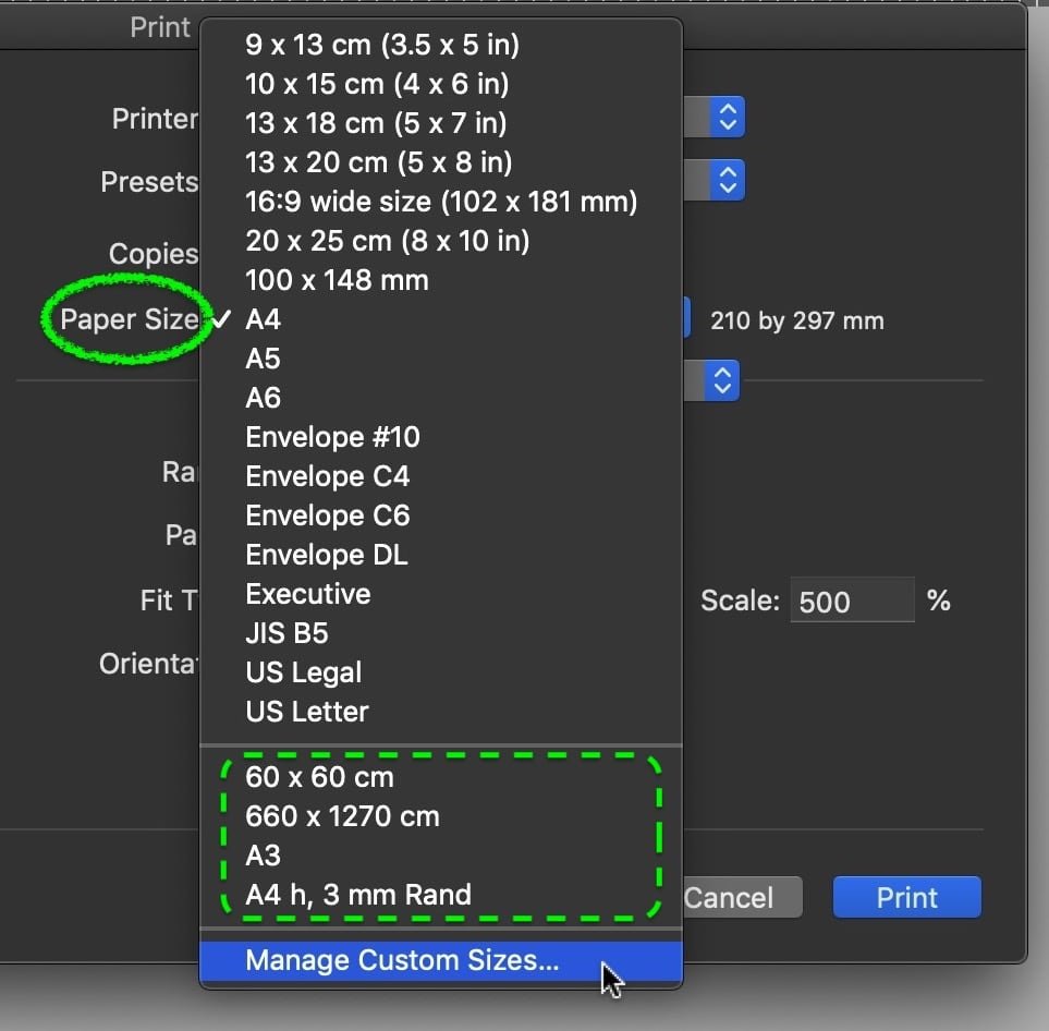
In this case it seems to be a matter of your printer hardware + its driver software, rather than a feature initiated by Affinity.
(sorry, I can't open V2. Also my print driver dialog & options may vary from yours).Possibly you need to create for your printer a custom sheet size of e.g. 420 x 210 mm first to be enabled to choose this as print sheet format. For instance:

Hi Thomaso, That was interesting - my image will fit on a US legal size page and my printer support the same page size so I can now print the image on one sheet of paper. Finally got there! Thanks.
-
Are there any Serif developers who understands engineering drawing?
-
9 minutes ago, thomaso said:
In this case it seems to be a matter of your printer hardware + its driver software, rather than a feature initiated by Affinity.
(sorry, I can't open V2. Also my print driver dialog & options may vary from yours).Possibly you need to create for your printer a custom sheet size of e.g. 420 x 210 mm first to be enabled to choose this as print sheet format. For instance:
Hi Thgomaso,
Thanks but I've tried various AD page sizes but the printer seems to ignore them. I'm pretty much convinced that it is a printer problem which I will have to check-out further. Thanks for your help.
-
28 minutes ago, thomaso said:
Do I understand right that you want to print on a sheet with 420 mm lengths which exceeds the limit of 297 mm (A4) of your printer … and thus treat the printer like one that can print 'endless' / on paper rolls? Also it's still unclear to me whether you finally want to get the full layout printed or just a part of it, cropped to an area smaller than your layout and sheet?
Can you show a screenshot of your layout page + a selected rectangle in size and position of the wanted print area + the print dialog (similar to my screenshot above but with rulers activated)?
Hi Thomaso,
Yes that is correct. Its a bit like printing on an endless sheet! I have attached the file of the image I want to print.
-
Thank you for your reply. I've probably made this sound more complicated than need be.
I drew a developed shape of a small cardboard box that just fitted on an A3 page. My printer (Epson L805) will only print A4. What I was attempting to do,
without printing on 2 sheets of A4, was to print on a sheet of A3 paper that was trimmed to 210mm wide and print out the full size image. I thought I could position the image at one end of an A4 page with the rest of the image running-off the other end of the page. My reasoning was that the off-page part of the image would also get printed on the longer sheet of trimmed down A3 paper.
This may be a printer problem rather than an ADV2 problem. I'm trying to research printing on longer sheets of paper for my particular printer but so far with no success.
Ant suggestions would be most welcome.
-
Is it possible to position an image on an A4 page so that only the part showing will print? If I select print 'Selection' it will centre it on the paper which is not what I want. I want the image to print exactly where I position it on the paper.
-
Thank you for this advice.
-
I have a black and white image that I reversed using 'Invert' which has it own layer. I now want to add some objects to the image and find that when I group the whole image the added object disappear. How do I combine the new object with the inverted image?
-
That was very useful but how would I know where to find such help? If there was some kind of link in the manual where you first look for this kind of help that would be great.
-
1 minute ago, Pšenda said:
If you mean application Help, it cannot be understood as a "Manual" - i.e. what and how to do. There are completely different instructions and how-to videos for that.
Yes I do mean application help but wouldn't it make sense to have some reference or link in the manual on where to find 'How to do'?
-
Hi Carl,
Correction it was the other way round so I went back and deleted the levels layer just leaving the original image layer and then made the selection. I then applied the Levels feature and it worked! Thank you for the advice.
One of the things about the manual is that it doesn't give a examples of using tools and features but just what they do.


Measuring/Area tool in ADV2
in Feedback for the Affinity V2 Suite of Products
Posted
Having just used the Area measuring tool to find the perimeter of an object. The object is a series of straight lines that is not a closed shape. The perimeter tool doesn't work on an open shape and the Cusp measuring feature will only measure one line at a time.
I'm suggesting that an extra feature that allows accumulative measurement to be added together to get a continuous perimeter of a series of lines that are not a closed shape. This could be used for the perimeter mode and the Cusp mode.
I would like to be able to measure the inside of a shaped box to work out the amount of material I would need to line it.