GarryP
-
Posts
11,047 -
Joined
-
Last visited
Everything posted by GarryP
-
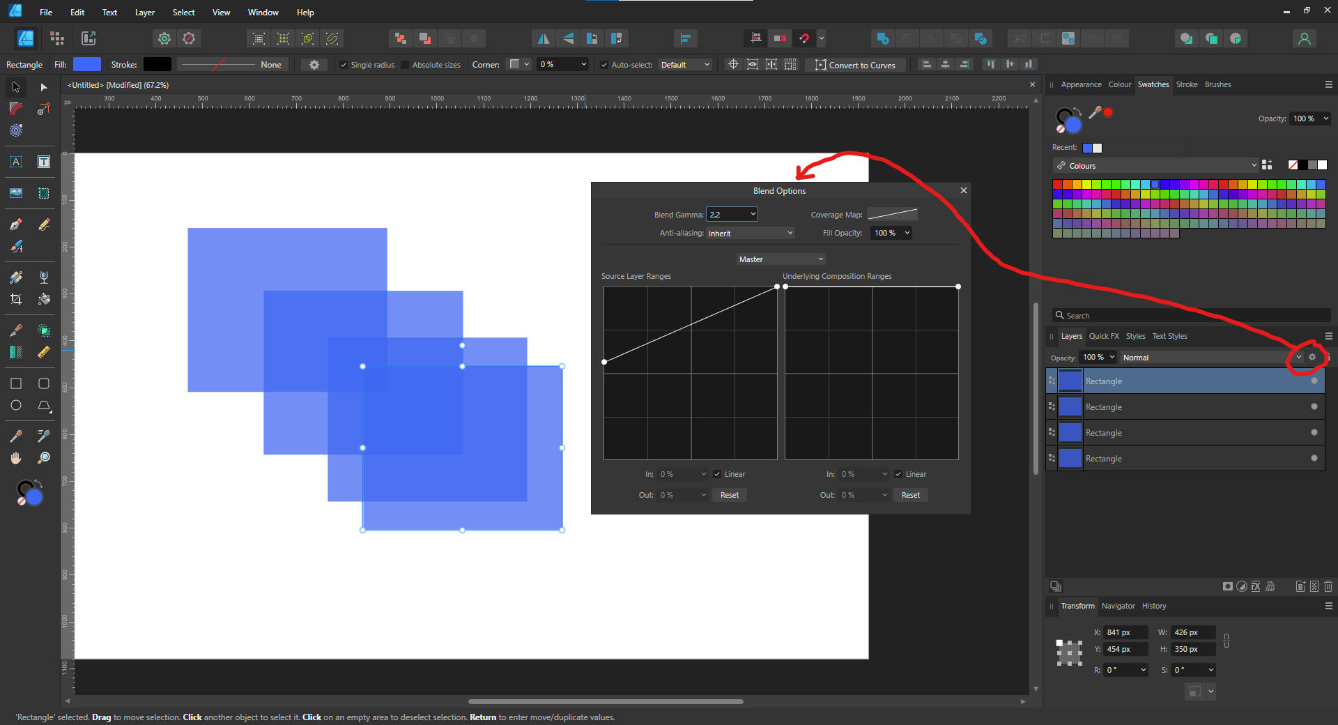
 Have you looked at the Blend Options for each layer?
-
key lines around image
GarryP replied to Michael Warren's topic in Feedback for the Affinity V2 Suite of Products
If you can give us a full-screen screenshot, where the Layers Panel is visible and the ‘problem layer’ is selected and visible in that panel, then we will have more of an idea of what’s going on. Otherwise we are missing a lot of useful information. If you can also share the document that would be even more useful. -
Stroke
GarryP replied to Mike in Hinderwell's topic in Affinity on Desktop Questions (macOS and Windows)
You’re welcome. That sort of problem is very easy to have so it’s one of the first things to look at. Another similar problem can be with the Layer Opacity as that can be changed by simply pressing one of the numeric keys accidentally – for instance, pressing the zero key twice in quick succession can lead to the selected layer being invisible = 00% Opacity. Because of this, it’s always worth checking the Layer Opacity, in the Layers Panel, just to see if something unexpected has happened there. -
Stroke
GarryP replied to Mike in Hinderwell's topic in Affinity on Desktop Questions (macOS and Windows)
Thanks for the extra screenshots – they help to make things much clearer. Everything you add to a document is a layer. In your first screenshot (of the new ones) you can see there are eight layers, each of which is an Image layer. You can see the type of layer by hovering the mouse pointer over the icon to the left of the layer thumbnail. The problem is that (in the first of your latest screen-grabs) your Opacity for the Stroke is set to 0%, which is invisible. -
Stroke
GarryP replied to Mike in Hinderwell's topic in Affinity on Desktop Questions (macOS and Windows)
It’s difficult to tell what’s going on from those screen-grabs - we can't see enough of 'what's going on'. What I can say is that any viewable Stroke applied to a Pixel layer will not be visible, whereas it would be visible with an Image layer. If that’s not the issue then we will need full-screen screenshots which include the Layers Panel with one of the ‘problem layers’ selected and visible in that panel. -
I believe the two options are there to help the user align the images in (at least) the two cases shown in my attached image. (I have exaggerated the effects.) I don’t think there is any ‘hard and fast rule’ about which you should choose, just whatever gives the best result.
- 1 reply
-
- 1
-

-
You can have multiple curves (not Quick Shapes) in a single layer by selecting all of the curves and using Merge Curves (as mentioned above) but all of the curves will have the same formatting (stroke/fill). Alternatively you can Group the layers. Alternatively you can put the layers in a Layer (capital “L”). The best choice will depend on your circumstances, the construction of the document, and any restrictions/requirements in the animation software. If you can share the document and give more exact requirements then someone should be able to help give you better information for your particular needs.
-
Save History is not a default setting
GarryP replied to KitKatKid's topic in Feedback for the Affinity V2 Suite of Products
See: https://forum.affinity.serif.com/index.php?/topic/174889-adding-save-history-with-document-as-a-default-in-app-preferences/ https://forum.affinity.serif.com/index.php?/topic/186793-save-history-with-document-opt-for-this-as-default-setting/ etc. etc. -
Uncorner tool/ Unbevel/ Unfillet tool
GarryP replied to Intuos5's topic in Feedback for the Affinity V2 Suite of Products
That sounds reasonable to me, without me thinking about it too much about possible problems. Recently I’ve been using the Node Tool and the Shape Builder Tool to do this sort of thing – see attached video – but it would be nice to have a quicker way. 2024-03-31 09-33-49.mp4 -
Uncorner tool/ Unbevel/ Unfillet tool
GarryP replied to Intuos5's topic in Feedback for the Affinity V2 Suite of Products
This sounds interesting, and is something that would have been useful to me from time to time, but I’m wondering how the user would specify where the “corner” is. -
Threads aren’t normally closed, as such. They are generally left open for comment so people can ask further questions, or give other advice, later. You can edit the title (long-click on the title) to add a prefix/suffix of “[SOLVED]”, or something like that, if you want to, but it’s not necessary.
-
Delete on right click menu
GarryP replied to Handyann's topic in Feedback for the Affinity V2 Suite of Products
You’re welcome. -
Thanks for sharing the document. There are so many misalignment issues with the drawing that I would be tempted to start again. Almost none of the walls or dimension lines are vertical/horizontal, and they ‘overlap’ in strange ways which could be causing some of the problems. Unless you are measuring things from the plan I would create the plan in one document, where you can specify/use the exact dimensions to make it easier to create things the correct size, and then place that document (linked) into another document where you can add the annotations, legend, etc. Also, I can’t tell where the measurements are taken from – outside or inside – or whether they are in feet or metres (I’m guessing metres as a 4ft bedroom isn’t very large). I’ve attached a quick mock-up (image and document) of how I might do it (I haven’t recreated the whole thing, just a bit of it). Note that: the document measurements are ‘real’, e.g. a 4m x 4.7m room is that size in the drawing; I’ve used Stroke Align Inside/Outside (as necessary) to create the walls (which are 10cm – one grid square – thick) and other things; each room is a single item which make it easier to draw and, also, makes it easier to use the Area Tool to find the area and/or perimeter if necessary; the windows, doors and stairs are repeatable items (probably better as Assets) which can simply be copied/resized as necessary. My version isn’t perfect by any means but it should be much easier to make this sort of plan from it. room-plan-example.afdesign
-
Wand tolerance changes
GarryP replied to AndyV's topic in Affinity on Desktop Questions (macOS and Windows)
If by “wand” you mean the Flood Select Tool then that’s how it’s supposed to work. Click to flood the area, drag to flood the area while changing the Tolerance. Check the Status Bar for more information. -
I’m pretty sure here’s an option for that in Settings / Assistant. Try this one:
-
See also this request: https://forum.affinity.serif.com/index.php?/topic/123831-arrows-and-other-shapes-in-the-middle-of-a-stroke/
-
Also, if you can share the AFDESIGN document then we will be in a better place to experiment with it and find out what the problem is.
- 36 replies
-
- 1
-
-
- affinity designer
- (and 2 more)
-
Also, your dimension lines (and many other lines) aren’t aligned with the grid so that’s making them look strange – you might want to turn Grid Snapping ON via the Snapping drop-down on the Toolbar. Once Grid Snapping is ON you will need to manually re-align the lines to the grid.
-
For the dimension lines, try drawing a simple line (with the Pen Tool) and changing the Start and End shapes via the Stroke Panel.
-
Delete on right click menu
GarryP replied to Handyann's topic in Feedback for the Affinity V2 Suite of Products
Its there on Windows too – see attached screen grab. @Handyann If you can show us a full-screen screenshot which includes the menu you are talking about then we will have a better idea of what you are looking at.
-
Thanks for the screenshots and extra information but we would preferably need the image itself so we can experiment with it to find a good solution for that particular image.
-
See: https://forum.affinity.serif.com/index.php?/topic/146025-cant-select-gradient-swatch-in-layer-effects-gradient-overlay/
-
Yeah, I think my advice would be to start again, after we find out what the original problem is and get more details about what the expected result should be.
- 36 replies
-
- 1
-
-
- affinity designer
- (and 2 more)
-
I’m not seeing any ‘missing corners’ either. There’s a green ‘L’ shape in the PDF which isn’t in the screenshot though. The ‘dimension lines’ have some strange ‘kinks’ in them and they don’t seem to be aligned to the drawing but no missing corners. Actually, looking at the PDF more, there seems to be a lot of ‘misalignment’ going on, and some other problems.
-
Welcome to the forums @Yumeropes The best solution in situations like this will often be different for different images so we need to be able to see what you can see in order to advise on what the possibilities could be. If you can show us an example image, and tell us which areas of the image you want to ‘extend/enlarge’, and tell us what you expect the result to look like, we should be able to give you some ideas.