stevenmiller
-
Posts
22 -
Joined
-
Last visited
-
Curves Adjustment: LAB Mode -> Desaturation Bug
stevenmiller replied to stevenmiller's topic in V2 Bugs found on Windows
@Ldina thx for clarifying, at least I know that it‘s not a windows version issue. I gonna look up for some online sources then, cuz it‘ll be nice to have some of your LAB color profiles as they come in quite handy. -
Curves Adjustment: LAB Mode -> Desaturation Bug
stevenmiller replied to stevenmiller's topic in V2 Bugs found on Windows
@Ldina@NotMyFault hmm, a little dissatisfying that Affinity couldn't make it work properly...but I guess if they don't consider this an issue we have to live with that inaccuracy.... Another thing: Does the Windows version of Affinity has less color profiles? You have a whole bunch, I even don't have Grey Tone as a drop down item, only have CIELABD50...
-
Curves Adjustment: LAB Mode -> Desaturation Bug
stevenmiller replied to stevenmiller's topic in V2 Bugs found on Windows
I have uploaded an .afphoto file in the attachment. Download and see for yourself. Just quickly toggle on/off the B&W adj layer and you will see that there is a tint left when the B&W adj is off. LAB desaturation.afphoto
-
Curves Adjustment: LAB Mode -> Desaturation Bug
stevenmiller replied to stevenmiller's topic in V2 Bugs found on Windows
@Ldina Thx for the suggestion. I forgot to mention that I tried this already: Conversion to Lab/16 does not change the result, still a cyan tint - using different images, using the channel mixer or curves adjustment. I know that there are other techniques to desaturate an image - that's not what I am trying to get it. My point is that the desaturation when setting AOpponent and BOppenent to 0.5 (no matter if curves or channel mixer), it does not fully desaturate, there is still an (almost not perceivable) cyan tint left. You can fully get rid of this tint by adding a b&w adj on top of this and setting cyan to 0%, but that's not my point. Shouldn't you get a fully desaturated image using above methods in the first place? Doesn't this indicate that curves and channel mixer in LAB mode do not work properly? -
Curves Adjustment: LAB Mode -> Desaturation Bug
stevenmiller replied to stevenmiller's topic in V2 Bugs found on Windows
By the way: to make the tint visible using on of the LAB desaturations methods, you have to add a black and white adjustment layer afterwards and set cyan to 0%. Then toggle of the b&w adj layer quickly on/off. -
Curves Adjustment: LAB Mode -> Desaturation Bug
stevenmiller replied to stevenmiller's topic in V2 Bugs found on Windows
@NotMyFault Thx for showing this alternative LAB method, but it produces the exact same result - a slight cyan tint. By the way: I did not literally "drag" the curves, I entered the exact value 0.5 as numeric input - and there is a slight cyan tint, hard to see I admit, but there is. This cyan tint is independent of the LAB desaturation method and the image used. Look at the two b&w images attached, one of them has a slight tint. You can only see the tint if you toggle on/off the layer very quickly - however, just looking a the tinted image does not reveal it, without comparing it to the fully desaturated image it's almost not perceivable - but it's there, and I think this is a bug in affinity. -
 Alfred reacted to a post in a topic:
Curves Adjustment: LAB Mode -> Desaturation Bug
Alfred reacted to a post in a topic:
Curves Adjustment: LAB Mode -> Desaturation Bug
-
Curves Adjustment: LAB Mode -> Desaturation Bug
stevenmiller replied to stevenmiller's topic in V2 Bugs found on Windows
@Alfred thx for the hint, I corrected this in the original post, I meant 0.5 of course. -
OS: Windows 11 AP: 2.4.1 Problem description: When desaturating an image with curves adjustment in LAB mode, the image is not fully desaturated but contains still a little color. That should not be the case, the image should be fully desaturated. Is this a bug? Does the curves adjustment in LAB mode is not correctly calibrated? Steps to reproduce: 1. Download the images attached (they are taken from https://en.wikipedia.org/wiki/HSL_and_HSV and correspond to Fig.13a and Fig13b) 2. Inspect the original (colored) image and the desaturated image (both from wikipedia). The desaturated version is the the original image in which the AOpponent-/BOpponent values are set to 0.5 (=neutral grey). 3. Reproduce the result in affinity photo by adding a curves adjustment and set mode to LAB. For AOpponent and BOpponent drag the curves such they are horizontal and have constant y-value = 0.5 everywhere. 4. Now compare the result to the downloaded black & white image (all images below). You will see that the reproduced image with curves adjustment still has a cyan tint. To verify this do next step. 5. Add an black & white adjustment and set all hue sliders to 0%. You will notice that only the cyan slider has an effect. 6. Toggle on/off the black & white adjustment and observe that the cyan tint will be removed when the b&w adj is active. When active the result looks like the downloaded b&w image, when b&w adj inactive you will notice the tint. This can be reproduced with any colored image. As a final step always add the b&w adj and toggle it on/off - you will notice that the b&w adj removes the cyan tint which seems to be left in any image that is desaturated with the curves adj in LAB mode. Why does it matter? The LAB desaturation method is the one that desaturates in a way such that the perceived lightness is preserved (i.e. for the human eye it looks exactly like the original image just without colors - kind of lightness untouched). The reason is that the LAB color model strictly separates "lightness" from "color" as opposed to HSV and HSL and other color models. But somehow in affinity the implementation does not seem to be accurate.
-
 stevenmiller reacted to a post in a topic:
Feature request: Bulk linking option for linking layers
stevenmiller reacted to a post in a topic:
Feature request: Bulk linking option for linking layers
-
stevenmiller reacted to a post in a topic:
Feature request: Bulk linking option for linking layers
-
CM0 reacted to a post in a topic:
Feature request: Bulk linking option for linking layers
-
GripsholmLion reacted to a post in a topic:
Feature request: Bulk linking option for linking layers
-
Frozen Death Knight reacted to a post in a topic:
Feature request: Bulk linking option for linking layers
-
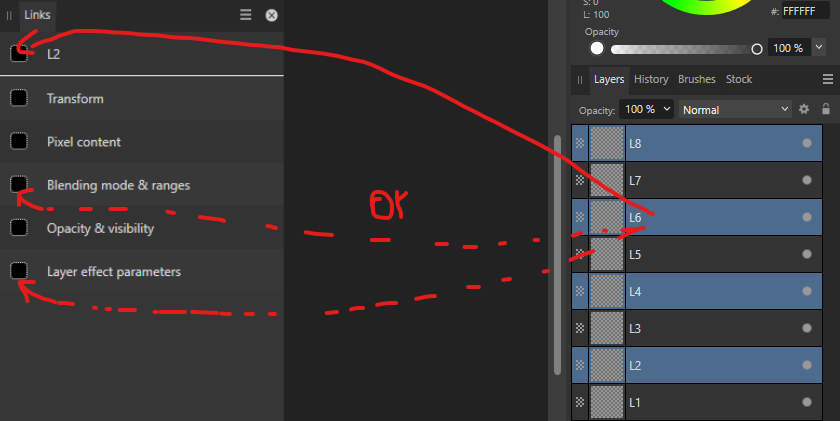
OS: Windows 11, Affinity Photo 2.4.1 Dear AP team, the ability of Affinity Photo to link layers via the Link panel is a powerful feature. However, the way it works via dragging layers is cumbersome. Moreover: The only way to link layers that are separated by other layers is by linking them one after the other. Suggestion: Make it more efficient by allowing bulk linking several (separated) layers at once. The bulk link feature could work something like this: Select all of the layers you want to link. On Link Panel: Dragging layers onto the dotted squares is cumbersome, instead they should be checkboxes that you can simply tick. The top checkbox should be called „ALL“ and ticking/unticking it should tick/untick all the checkboxes for the features below. If you only want to link some features you can selectively tick the checkboxes below the top line of the Link Panel. That‘s it! It would make life much easier.
-
Info panel shows wrong LAB values
stevenmiller replied to stevenmiller's topic in V2 Bugs found on Windows
Hi, @Hangman, true, you get values even working with a LAB document for the same reason. If the original image was created in (or converted to) RGB/8 the color gamut is restricted to RGB/8. Converting the document from RGB/8 to LAB/16 document cannot change that or restore any lost information. 1. Using the above example you can use LAB/16 format and create the (L,A,B)=(50,-128,0) colored rectangle with vector shape tool. Then export this as an image as .tiff file with LAB/16 color profile. 2. When opening the .tiff file, the info panel will show the correct (L,A,B)=(50,-128,0) values. But once you convert it to RGB/8 and then converting back to LAB/16 the info panel will always show (L,A,B)=(56,-43,9), simply because the conversion to RGB/8 will lose the color information past recovery. What happens during the conversion is: (L,A,B)=(50,-128,0) gets mapped to (R,G,B)=(0,155,116) from the bigger LAB gamut to RGB gamut - this RGB representation of the original (L,A,B)=(50,-128,0) value triple is already an approximation (the original color info is lost). When converting back from RGB to LAB the triple (R,G,B)=(0,155,116) gets mapped to (L,A,B)=(56,-43,9) because the original info is lost for good. -
stevenmiller reacted to a post in a topic:
Info panel shows wrong LAB values
-
Hangman reacted to a post in a topic:
Info panel shows wrong LAB values
-
Info panel shows wrong LAB values
stevenmiller replied to stevenmiller's topic in V2 Bugs found on Windows
@Hangman thx for the info. But finally I figured it out, the values in the info panel are not shown in percentages. And there is no bug. The reason is that LAB/16 has a bigger color gamut than RGB/8. Any image that has RGB/8 format cannot have the full range of LAB values. It is just as simple as that. U can simply check as follows: 1. Draw a rectangle (vector shape). 2. Color panel: switch to sliders, choose LAB, set values (L,A,B)=(50,-128,0). That colors the rectangle green. 3. Convert back and forth between LAB/16 and RGB/8 (via Document> Convert Format) and observe the info panel. 4. Observe LAB values in the info panel: In LAB/16 format it shows (L,A,B)=(50,-128,0) vs in RGB/8 format it shows (L,A,B)=(56,-43,9). 5. Use online color space converter to check that this is indeed the result of the color space conversion. e.g. use https://www.easyrgb.com/en/convert.php#inputFORM -
NotMyFault reacted to a post in a topic:
Curves adjustment, choose color channel for picker
-
NotMyFault reacted to a post in a topic:
Color Picker BUG: curves adjustment, LAB mode, color picker picks wrong values
-
Thx for the hint, I supported your request for adding an additional option (so it seems you ran into the exact same issue a few months ago...). Good advice, thx, that workaround is a good way to cope with the missing color picker option for adjustments! The good thing about your workarounds is they work in any setting: With blend ranges/luminosity mask you can always target specific luminosity ranges and with your other workaround you can always target specific colors - very useful tips!
-
stevenmiller reacted to a post in a topic:
Color Picker BUG: curves adjustment, LAB mode, color picker picks wrong values
-
stevenmiller reacted to a post in a topic:
Color Picker BUG: curves adjustment, LAB mode, color picker picks wrong values
-
I support this request, have the exact same issue with the workings of the color picker. Please add to the documentation and an option for the channel.
- 1 reply
-
- 1
-
-
stevenmiller reacted to a post in a topic:
Curves adjustment, choose color channel for picker
-
@NotMyFault The advice with the blend ranges/luminosity mask is quite useful - thanks for that. That addresses how to target specific tonal ranges. However, the color picker in LAB is not useful for color manipulation in AOp/BOp-channel. If Affinity would change the standard behavioiur of the color picker in LAB to pick the point on the curve based on the value of the channel that you have chosen (e.g. in AOp-channel it should be based on the AOp-values not on L-values), then the color picker would have some practical use as you would be able to target a "color" and shift that color to another desired color (of course restricted to the available colors is that channel: for AOp-channel that would only be colors ranging from green to red). Otherwise: What is the use of the color picker in LAB for the AOp/BOp-channel?
-
@NotMyFault That is exactly my point! The fact that the color picker does always picks points on the curve based on lightness values is true (I know), but that does not make it any better, and in case of the LAB mode the color picker's value picking is not of any practical use. That is why the the color picker should be modified for the LAB mode and why I call it a bug. If you follow my example you get my point. Using the color picker in the above example for the AOp-channel, for each grey stripe the color picker will pick a different point on the curve (based on lightness values), but what the color picker should do: It should pick the middle point on the curve for the AOp/BOp-channel, no matter where you click on the greyscale picture. This is the only meaningful pick. Even James Ritson got confused about this behavior: In his tutorial about the LAB color model he mistakenly explained that picking a point on the left on the curve (he used the BOp-channel) and dragging it down will add blue to the shadows. But that is not what you do: You add blue everywhere in the picture (not only in the shadows), to be precise: Everywhere in the picture where the BOp-value is in the ballpark of the input value on the horizontal axis corresponding the to the picked point on the curve. This confusion is caused by the misleading "standard behaviour" of the color picker in LAB. The standard behavior just is not useful in LAB. That is my point. No misconception on my side: I know how the curves works, by the way: LAB uses values from -128 to 127 for AOp/BOp channels and 0 to 100 for L-channel and maps them internally from 0.0 to 1.0. Technical term for this is Normalized Values. For clarity: In my example above I only refer to the Original LAB values - I assume these easy linear mapping can be done by everyone in his head; graphically in the curves diagram it just means putting the -128 on the left, the 0 in the middle, and the 127 on the right of the horizontal axis, similarly for the vertical axis - it seems that you did not notice that I was referring to the original values only.