

NullAllocationError
-
Posts
23 -
Joined
-
Last visited
Posts posted by NullAllocationError
-
-
Sometimes it's useful to be able to apply a certain change to or involving a number of layers that for visual layering reasons one doesn't want to put in the same group (to tie this in with an earlier suggestion of mine, this can be important for snapping); symbols could theoretically do a lot of this, but they're kind of messy and inelegant to work with, especially for certain applications.
What I am suggesting is to add another tab similar to the one used for layers, symbols, etc., this one being a list of special "groups" that unlike normal groups do not act as a layer (/influence the layering order) or appear as such in the layers menu. When one clicks on such a grouping's symbol in the tab, it is selected and the tab shows options for "add layer to group from layers menu" and "remove layer from group" (instead of its default option to create a new example of whatever these non-standard groups would be called, or the option when layers have been selected otherwise to create a group from said layers), and while this grouping is selected in this way, while one cannot reorganize any of the shapes involved layer-wise, it limits the context for most operations to just the layers grouped in this way, allowing for easier synchronization of certain effects.
-
It's mildly annoying to be unable to control the stroke pressure exactly in Affinity Designer; wanting to somewhat align how thick the stroke is on two objects along a certain point is pretty much impossible. However, I've realized that there's a preexisting design paradigm for controlling properties of objects that exist within shapes but which have their own node points: that of the controls used for gradients by the Fill tool.
As such, I'd like to suggest that, either via the stroke options in the context toolbar or as a tool in the regular toolbar, there should be a way to control the stroke pressure of a shape with a node-based system, operating as follows:
With this tool active, each selected curve or other shape has a line surrounding it, representing the stroke's path. This line has nodes along it, each setting what the stroke pressure should be at that point along the line; this is shown as the width of the node's square shape perpendicular to the line, and can be adjusted either by placing one's mouse just to the side of the node and "pulling" on the symbol that pops up or by clicking on the node and manually typing in a value for the stroke pressure. By default, curves have just a start and an end node, which for closed curves is represented as a "fused" node, where half the node is the start-size and half the node is the end size; an arrow symbol might also be useful for matching this to the existing stroke pressure control system. As for how this works with shapes that have an inner portion cut out or distinct shapes that have been combined via the add operation, I feel that if a shape contains multiple distinct stroke portions, those should be controllable separately (admittedly, this is functionality Affinity doesn't yet offer even via the already-extent stroke pressure control method), and thus should have their own line with nodes.
-
Simply put, an option that lets you designate a layer to be prioritized for snapping to (ignoring non-prioritized shapes close to the area where you're trying to snap if there are prioritized shapes there); I imagine it as simple right-click options accessible while mousing over the layers panel: for layers that haven't been designated for snapping, it'd give the option to make them one of the layers to snap to, while for layers that have already been designated, the right-click prompt would be to no longer prioritize them for snapping. An additional button next to the general snapping on/off button would let you reset the list of layers to prioritize snapping to entirely, effectively turning it off until you redesignate a layer as a priority for snapping.
This'd solve some of the issues I've had where due to several shapes being close together (for example due to shading layers on top of the layers they're shading) Designer fussed back-and-forth over which of two other shapes it'd try to snap to, completely refusing to snap to the shape I was actually trying to snap something to.
-
That works perfectly for shading single shapes, but unfortunately, if attempting to apply the Multiply shape to a group of shapes like that, it just leads to adding the Multiply shape to the group of shapes (as one would expect), the Multiply shape's effects extending past the rest of the group.
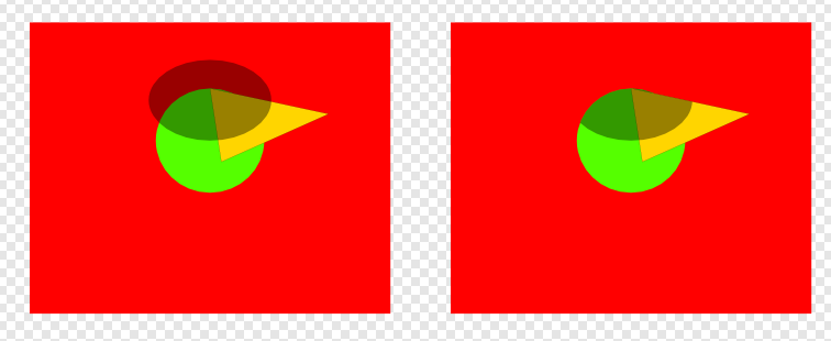
EDIT: For reference, here's a similar comparison picture to before, this time with how B affects group A (consisting of shapes Aa (green ellipse) and Ab (yellow triangle)) and shape C if shape B is not manually edited on the left, and how I'd want them to be affected on the right. Effectively, what I'm asking (now that I've found the right terminology again) is if there's a way to clip the Multiply shape to a whole group, rather than just a single shape?

-
I know that it's possible to do some tricks with using a copy of the layer one wants to apply a blend mode shape's effect to (optionally kept synchronized with the symbol feature) as a mask for the blend mode shape, but that's circuitous (and somewhat lag-inducing when that means copying complex layers) and is a lot of effort for something that workflow-wise should probably be fairly simple, so it makes me feel that I'm probably missing something when it comes to the correct way of doing this.
To clarify, let's say I have a shape A that I want to apply a shadow to using shape B (which has its blend mode set to Multiply), but I don't want shape B's darkening effect to apply to any part of shape C, which is beneath A. Do I need to make shape B match shape A's, well, shape perfectly (either via use of a copy of shape A as a mask, or via manual editing), or is there a trick to get Affinity Designer to ignore the effects of shape B on shape C, which is outside of the A-B group?
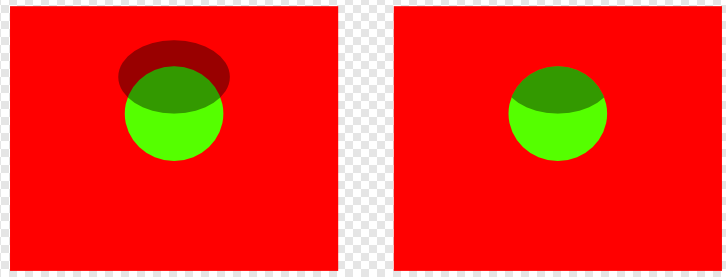
Below is a picture showing the situation, with shape A being the green circle, shape B being the darkened circle above it, and shape C being the red rectangle; left is what happens if I don't edit the shape down (regardless of use of groups), right is what I would like to have happen.
-
Let's say I have a number of layered shapes. I want to ensure one node of shape A, at the top of the pile of shapes, is aligned to a side of shape B, near the bottom. To ensure shape B doesn't get out of alignment with other shapes, I have it grouped, or shape A is part of a compound with another shape, or some other situation where keeping both objects selected at the same time (to take advantage of the "align nodes to selected curves" snapping option) would require rearranging the layering of the shapes.
In situations like this, is there a convenient way to "tell" Affinity Designer that I want to specifically snap to shape B rather than any of the other layered shapes (since the previously-mentioned "remove shape A and B from their groups, compounds, etc. so you can select both, turn off all snapping options other than the selected curves one, snap, put shapes back into their groups, compounds, etc." is rather tedious)? Being able to mark a layer to snap to would be very convenient.
-
As far as I can remember, I simply used the pen tool, and drew a horizontal line, followed by a vertical line. Then I resized it and clicked it with the Artistic text tool. No clue what I did differently that's causing the bug (?) to not occur when I try the same steps now.
-
9 minutes ago, loukash said:
That is… there is a Pinning panel in Designer but it's only accessible by "happy accident" if you click the "pinned" icon next to the pinned object in the Layers panel. Then you can adjust all pinned attributes. And make sure to save a new Studio Preset with the Pinning panel active so that you can recall it anytime. At least that's how it works on Mac. (Not all of such "happy accidents" are cross-platform…)
So, it's a pinned inline object, but for some reason it lives outside the text frame. That looks like a weird bug to me.
That's extra weird, because here on Windows, I can't even see the "pinned" icon in the Layers panel.
-
I've been trying to figure out the specifics of how text paths work when used to align shapes to them, and I've run into an issue that I can't quite understand. In the document I've uploaded here, when I try to paste an object into the text path in the third group from the bottom, that object will, seemingly no matter what (regardless of the path being adjusted or being made closed, the start/end handles for the text path being adjusted or a different shape being pasted in), end up with a position entirely outside of the text path, with much lower X and Y values than any point on the path itself. Can anyone help me figure out what's going wrong here?
Text paths for alignment of objects along paths experimentation.afdesign
-
The first image here shows a simple T-shape, made by grouping together a vertical line and two bent mostly horizontal lines. The second image shows the desired result of applying a simple striated line brush to it. Weird discontinuities at the join are kept to a minimum because it was made by copying the vertical line and joining one copy of it to each of the horizontal lines, and then grouping the two results. The third image shows what happens if I attempt to adjust the vertical length of the shape as a whole or adjust the horizontal line segment: regardless of the direction of the curve, and despite it being set to repeat, the brush deforms so the striations aren't aligned anymore. You'd think the direction of the curve would determine where Affinity Designer starts with the application of the brush, but no, it seems to be trying to apply it from the middle, if the way the placement of the striations adjusts if you change the curve's length at all at any portion is any indication.
Is there a way to either a: adjust the ends of a brush in such a manner so as to allow the line segments of the T-shape to be kept separate but without creating discontinuities at the join or b: fix the point of application of the brush in place along the curve so the alignment of the striations doesn't get messed up?
-
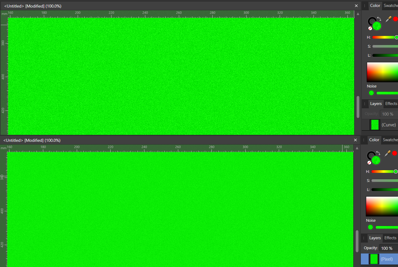
A simple example, comparing the pre-rasterization version and the rasterized version (I was ballparking the 1/10th stuff for emphasis):
-
58 minutes ago, loukash said:
If you want to use advanced design tools, make yourself familiar with their advanced functions. Like nesting and clipping layers.
add noise live filter AND clip it.afdesign
Okay, that's fair enough, but it still doesn't allow for noise that varies along gradients, nor does it explain why the noise from the color panel doesn't just remain at the same level if rasterized or exported, which is kind of the thing I want to track down the reason for, because having to use a workaround because the conveniently located, actually-making-sense-for-workflow method isn't behaving sensibly seems rather silly.
-
The issue is that it's a full-screen filter that I'd have to edit it down if I wanted to apply different amounts of noise on different shapes, thus there is even less reason to copy that one filter all over the place from a separate document into whatever document I'm working instead of the simpler and more versatile solution of just copying whatever shape I want to add noise to, adjusting the colors to be suitable for use as a Multiply layer and copying it until it reaches the desired amount of noise. It solves my problem about the same amount as that second solution, which is to say it still takes an absurd amount of work just to correct a weird issue that occurs for no clear reason when exporting or rasterizing.
The question of "how to make that filter layer" is mostly just curiosity, it's the question of "why is a separate program needed to access this functionality that this program already supports".
-
Thank you for the effort. The filter you provided is unfortunately unsuitable for my needs, but it is kind of curious that despite that filter being usable in Designer, I can't actually find a way to make it in Designer. As for how I was making the noise, I am indeed using the color panel, as that allows me to have a gradient that goes from a relatively "clean" color to a dirtier, more grimy-looking tone.
-
Noise filter layers are not a thing in Designer as in Photo, at least as far as I know, unless you mean "add a layer that's a duplicate of the one I want to give noise to and use the Multiply blend mode to make it effectively transparent except for noise"; either way, that'd be doable, but a pain to do for every layer I want to work with (and doesn't seem to play nicely with some effects), which is why I'm asking whether there's any way to track down the actual source of the noise reduction and turn it off.
-
While I've heard that there's a known issue that noise is non-representative at zoom levels other than 100%, that doesn't seem to be the issue here; in fact, the amount of noise seems fairly consistent between zoom levels, if anything. However, the issue I'm having is that, if I add noise to any shape, and attempt to export it to .png or rasterize it, the result always seems to have far less noise, about 1/10th, and consisting entirely of far smaller specks. Testing this out with rasterization shows that the change that occurs is visible regardless of zoom levels, to boot.
This is an issue, given that I like to work with noise-heavy shapes, and I can't dial up the noise any further to compensate for this change. Is there a setting somewhere that's responsible for this?
-
8 minutes ago, Joachim_L said:
Do you mean a compound? Select both your element and the hole, keep the Alt key pressed and click on the Subtract button.
No, I specifically want to avoid a compound; I mentioned the issues I have with using Subtract for this (alters the appearance of shapes with the 3d effect applied to them, gets finicky with layer ordering and grouping) in my original post. What I'm looking for is effectively a way to create an inverted version of a mask.
That being said, I ended up finding the solution I was looking for: the Erase blendmode.
-
For a few applications, e.g. with shapes with the 3d effect, it's important to be able to visually "cut" a hole in the shape without actually altering the original shape. It's also useful in general to be able to remove a shape's area from a drawing without having to mess around with subtracting the shape or shapes from (especially since the order of the layers sometimes gets messed up if you don't subtract the shape from each shape individually, which means a lot of copy-pasting). So I'm asking if it's possible to set a shape to act as a visual "removal" effect. If it's not clear what I mean, I mean that, if a shape is set like this, the area where the cutting-out shape is should show the background, visually overriding layers below it that might otherwise be visible there.
EDIT: Turns out the Erase blendmode is what I'm looking for.
-
This is a bit of an oddity in Designer I noticed: extending one handle out of a node using the pen tool + alt and then releasing alt so it can snap to a guideline for precise alignment of your now actually curved curve works fine. If you try to extend the other handle out and snap it to the same guideline point (to make it so your node has symmetrical concave lines on either side), you need to do it in two steps, because you need to keep alt held for one step or it will try and force the handle you already snapped in place to be on the opposite side of the node. As such, after you click to release the handle so Designer will stop trying to force the other handle to the other side of the node, you then have to drag it again after selecting the node again.
Am I missing something blindingly obvious again about how to do this in one step, or is this just a minor control scheme oversight/oddity?
-
I was wondering if it's possible to, when adding a point to a series of curves, align the placement of the new point so that while it snaps on the nearest preexisting line of the shape, it keeps either the horizontal or vertical position of a previously-made point.
While I'm aware this can be done manually after placing them, I'm curious if there's a way to do so while placing the points, since symmetrically adding points to a shape (so that I can adjust the angle of an endpoint without changing the angles in the rest of the shape) is pretty common in my workflow.
[EDIT]: I seem to be cursed to be unable to find the solutions to questions while searching or pressing/hovering over buttons until after having posted about it. The Snap option to "align to curves of selected nodes" accomplishes exactly this.
-
I have attempted to download the trial version of Affinity Designer, but (and this holds no matter whether I download the newest version or an old version of it (and yes, I have made sure to clean the previous download out when I try to reinstall it), or even Photo instead of Designer), I get a message to the effect of "The program or feature [address in my temporary appdata that features AffinitySetup as one folder name] cannot start or run due to incompatibility with 64-bit versions of Windows." from my computer, alongside "Failed to start setup. Please contact technical support." from the program itself. Now, to my understanding, Affinity is only available for 64-bit systems, so this is a bit odd. Any thoughts with regards to how I can resolve this?
EDIT: Never mind, turned out it was the ".NET 3.5 being active" issue, and I simply hadn't turned it off right.


Is there a way to use blend modes to average hues or "push away" a hue from another hues?
in Pre-V2 Archive of Affinity on Desktop Questions (macOS and Windows)
Posted
This is mostly for the sake of lighting. Colored lighting looks nicer if represented with highlights tending towards the lighting's color and shadows contrasting that lighting's color; or, to put it another way:
This seems like it should probably be an obvious application of blend modes, but I have so far not been able to figure it out, so I'd appreciate any help people can give. I'd sort of hoped the Hue blendmode would work for this, but it changes the luminance more than the actual hue.