pbasdf
-
Posts
74 -
Joined
-
Last visited
Everything posted by pbasdf
-
I have had similar problems in the past. I would open a file in Affinity Publisher (generally the file would be in a Google Drive folder - I know, not recommended, and I've stopped using GDrive) and I would get the "Loading 1 document" message. Going to Finder, I'd see that iCloud was downloading files. If I sat and watched, the number of download files and the total download size would go up. As soon as iCloud finished the download of all the files, Affinity would open the document. At first I thought this was due to 'linked files' in my Affinity document being downloaded from iCloud as part of opening the document. But if I clicked through the iCloud folders, I could see all manner of files being downloaded, all of which were completely unrelated to my Affinity file (which, when I checked, had no links to files in iCloud anyway). This all occurred at a time when my internal SSD (the system disk) was very close to capacity. After I moved everything to a larger SSD (as system disk), the problem went away. That might just be coincidence - but it might be worth checking whether your system disk is getting full and clear it out a bit if necessary.
-
Not sure if I've understood your problem correctly, but if you select the frame for the cutline, then in the Text Frame panel select "Ignore Text Wraps", does that achieve what you want?
-
Publisher text in a frame changing formatting
pbasdf replied to Sukavi's topic in Desktop Questions (macOS and Windows)
Hi @R C-R I notice that the frame in question is identified in the layers panel as Shape Text, not a Text Frame. If (in AfPub 2.5.6) I create a shape and then convert it to Shape Text, it has the same problem - double clicking the blue dot does nothing. I'm not in the beta programme - @MikeTO could you check whether AF-4290 fixes it for Shape Text? Phil -
In the case of your SVG import, you can merge the text into a single frame (in Publisher) by linking the frames, as follows: 1. Select the (art) text frames that you want to merge. 2. Right click and select "Convert to text frames". 3. Starting with the first frame in the sequence, click on the text-flow triangle on the right hand side of the frame. 4. Click on the next frame in the sequence. There is no apparent change, but the text is now in a single "story", flowing from the first frame to the second. 5. Repeat steps 3 and 4 to join frames 2 and 3, then 3 and 4, etc. 6. The text is now all one story, flowing from each frame to the next. 7. Delete all but the first frame. The text in the story will be intact, in the first frame, but it will overflow. 8. Resize the first frame to accommodate all the text. 9. Adjust leading or before/after spacing to get the lines in the right places. If you've got a lot of these to do, it might become quite tedious (or you might get into a rhythm...)
-
One possibility - it looks like you might have swapped the fill and stroke colours: in the Context toolbar, the fill is showing as 'no fill', and in the Colour panel, the stroke is showing as black (and the fill as 'no fill'). Try switching them back by selecting the text and clicking the curved double-headed arrow above right of the two colour wells on the Colour panel.
-
In the first image, the layer opacity (at the top of the layers panel) is set to 50%, while in the second it is 100%. Does that explain the difference you are seeing?
-
Having looked at the PDFs produced with different settings, I think the issue might be related to the dimensions of your page, ie. very wide. It looks like Affinity composes a single 'image' from all the images and then applies the Curves Adjustment to that one image. But I think that image is so wide it exceeds some internal limit (16384). The DPI is adjusted so that the 'image' is max 16384px wide. That's my guess as to what's happening. If it helps for your situation: if you apply the Curves adjustment to each image layer separately, then the result is seven separate images each at 150 dpi.
-
Exporting to PDF problems...
pbasdf replied to 4Candles's topic in Desktop Questions (macOS and Windows)
You have selected 'All Spreads' in the 'Area' of the export settings, so APu generates a PDF in which each page is composed of a spread of 2 pages from the original document. If you change the Area to 'All Pages', your PDF should have a separate page for each page of the document. Sadly APu forgets this setting after each export, so one has to remember to change it every time. -
Reset text bounding box in Publisher?
pbasdf replied to Silenceisgrand's topic in Desktop Questions (macOS and Windows)
Double clicking the edge of the bounding box should do it. -
What is AP's WORKING color space?
pbasdf replied to KLE-France's topic in Desktop Questions (macOS and Windows)
This Spotlight article might be of interest: https://affinityspotlight.com/article/raw-actually/ In the paragraphs headed "Colour" it tells us -
I don't use Photo so much, so I hadn't noticed the absence of the fill mode option - but I agree, I can't see it myself. Likewise, I can't help with any way to change the default fill mode. Sorry.
-
There are two different ways to work out what's "inside" a given curve, which give different results (particularly where there are overlaps). Try Layer --> Fill mode --> Winding (Non-Zero).
-
Export to PDF file sizes vary
pbasdf replied to Gigatronix Pete's topic in Desktop Questions (macOS and Windows)
Hi @Gigatronix Pete It looks like this is a consequence of the FX (Outer Shadow) applied to the 'PCB Connector' group that @carl123 has highlighted. I think what is happening is that the outer shadow is causing everything below it in the layer stack (which is everything except the title text) to be rasterised - into a single layer (hence the relatively small size of 28Mb). When you change the document size, the PCB Connector group is no longer within the canvas bounds, so it is not included and hence does not cause the rasterisation. Instead, all of the many layers that make up the 'Cables' group and the 'Connector Cable' group are included separately in the PDF. As there are many of them, and they are each quite high resolution, the file size grows to the whopping 228Mb. A quick fix would be to export using the 'PDF (Flatten)' preset (which will rasterise everything, including the title text). If that's no good, you could apply a similar Outer Shadow FX to the 'Cable Connector' group to cause that to rasterise independently of everything else (if you don't want a drop shadow on that group, just make the offset, radius and intensity all zero). Or you could copy that group (to preserve an editable copy) and then use Layer --> Rasterise. There may be better fixes others can suggest. -
Hi Steve, Difficult to tell from the video, but could this be a result of Publisher applying the same scale, rotation and relative placement to the new image as was applied to the old image? That's certainly behaviour that I experience and have to remedy. To save resetting them one by one, does this work: 1. Select the Picture Frame Tool (shortcut F) 2. Use Select --> Select Object --> Picture Frames (from the menu bar) 3. In the Context Tool Bar, select Properties and then set scaling and anchor for all the picture frames
-
Affinity Suite: Alpha transparency calculation
pbasdf replied to Pyanepsion's topic in Desktop Questions (macOS and Windows)
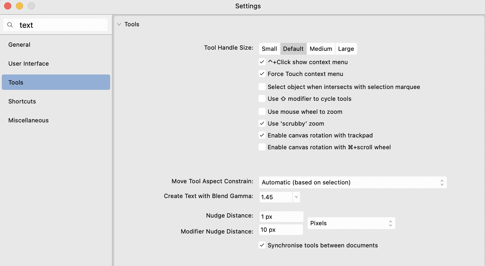
I haven't tested it, but I think this might be covered in Settings -->Tools --> Create Text with Blend Gamma:
-
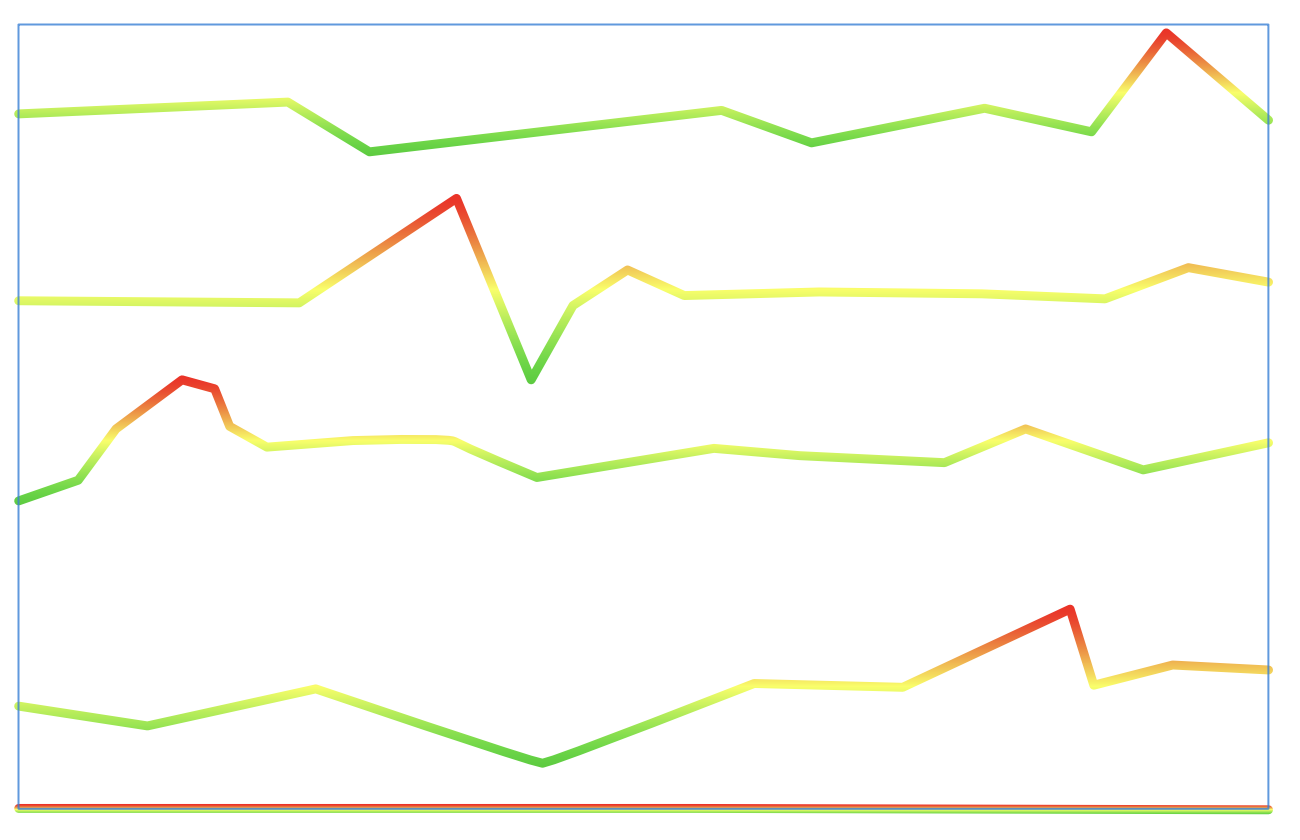
Might this work for your situation - leave the lines as black strokes, select them all and apply a Gradient Overlay FX? You can set the orientation to 90 degrees so the overlay is applied vertically. You can fine tune the FX on one line and then use Copy/Paste FX to apply it to all the others. There are a couple of downsides: 1. The "length" of the gradient is set relative to each particular object, so the "top" of a line will always be one end of the gradient and the "bottom" will be at the other end - even if the absolute height difference is much less than for the other lines. Even a perfectly horizontal line will have the top edge in one colour and the bottom edge the other (see pic). You might be able to finesse this with the scale and offset adjustments in the FX panel. 2. I believe using FX will result in rasterisation on export.
-
I can get "Snap to Object Geometry" to work when using the node tool, but not the move tool. No luck with "Snap to Shape Key Points".
-
exporting and scales not working
pbasdf replied to 3dGuy's topic in Desktop Questions (macOS and Windows)
I believe the issue stems from Blender using a different DPI setting for its SVG import. They use 90 (see for example https://projects.blender.org/blender/blender/issues/107130#issuecomment-928885), whereas Affinity uses 72 in the export. 72/90 is 0.8, which explains why your 1m square in Affinity ends up as 0.8m square in Blender. So the solution might be to change your export DPI in Affinity to 90. -
Hi Kip, Are you using any adjustment layers or FX? They can cause the text to be rasterised (even if the export options don't).
-
Hi Peter, I looked at the PDF for the green text/green background that you posted above. From what I can see (but I'm no expert), it sets the fill colour only once and uses that colour for both the rectangle and the text. See below (Comments after # are mine): /GS0 gs # set the 'graphics state' - in this case just configuring overprint /GS1 gs # ditto - in this case clearing any SoftMask 0.623529 0 1 0 k # Select CMYK colour space and set the current fill colour to 62%C 0%M 100%Y 0%K 70.8661 638.012 453.543 133.042 re # Draw a rectangle f # Fill it with the current colour 70.8661 638.012 453.543 133.042 re # Draw another rectangle (the stroke 50pt stroke) 120.866 721.054 m # move to the inside edge of the stroke 120.866 688.012 l # draw round the inside 474.409 688.012 l # ditto 474.409 721.054 l # ditto h # close the inside of the stroke f* # fill that with the current colour /GS0 gs /GS1 gs q # Save the graphics state 1 0 0 1 88.3058 687.353 cm BT # Begin text /F0 48 Tf # Select the font 0 0 Td # Set the text position [()-0.2()-0.2()0.2()-0.2()-0.5()-0.2()-0.1()-0.5()0.1()0.2( )0.2(\n)0.2()-0.2]TJ # Write out the text ET # End text Q # Restore the graphics state Line 3 appears tome the only line specifying a colour. So I suspect the problem must lie with your printer driver. Are you using the most up-to-date driver from Canon's website? Are you using the Postscript driver or another one? Phil
-
Long delay before export progress popup appears
pbasdf replied to MikeTO's topic in Desktop Questions (macOS and Windows)
FYI, in case it's relevant and helpful, I have had similar issues with a publisher file with linked resources on Google Drive. I have G Drive configured to sync locally so the files should all be available - and thanks to the menu bar icon animation, you can see when G Drive is syncing: nothing showing at the time. I've also had similar unexplained delays when creating Packages. The only other culprit i had in mind was fonts: I still get occasional spinning beach-balls when opening the font list in publisher, which normally clear after a while (usually tens of seconds, occasionally longer). I wonder if the export process kicks off a similar hunt for font files which for some reason stalls? I'm running Publisher 2.4.0 on Sonoma on 27" iMac, btw. -
Preflight for CMYK 0,0,0,100?
pbasdf replied to mykee's topic in Desktop Questions (macOS and Windows)
As a quick visual check, you can switch to the Photo persona, then in the Channels panel, switch off visibility for the K channel. Then scroll through all the pages. If you have any rich black text/images, they will still be visible. Everything that is pure K will disappear. Remember to switch the K channel visibility on again before switching back to Publisher persona - I always forget that. That won't overcome the export conversion issues highlighted above and elsewhere, but it will at least give you a visual check that you are starting the conversion process with pure K in the right places. -
Just to note that you mention Fogra 39 but your screenshot is Uncoated Fogra 29.
-
Why do my fonts have not fill?
pbasdf replied to Zap's topic in Desktop Questions (macOS and Windows)
Have you accidentally activated X-ray view mode? Resetting to Vector with View -->View Mode --> Vector should bring the colours back true. -
Autoflow pdf pages in Publisher
pbasdf replied to Edward L's topic in Desktop Questions (macOS and Windows)
Slightly - see this answer to a previous question: