purplie
-
Posts
26 -
Joined
-
Last visited
-
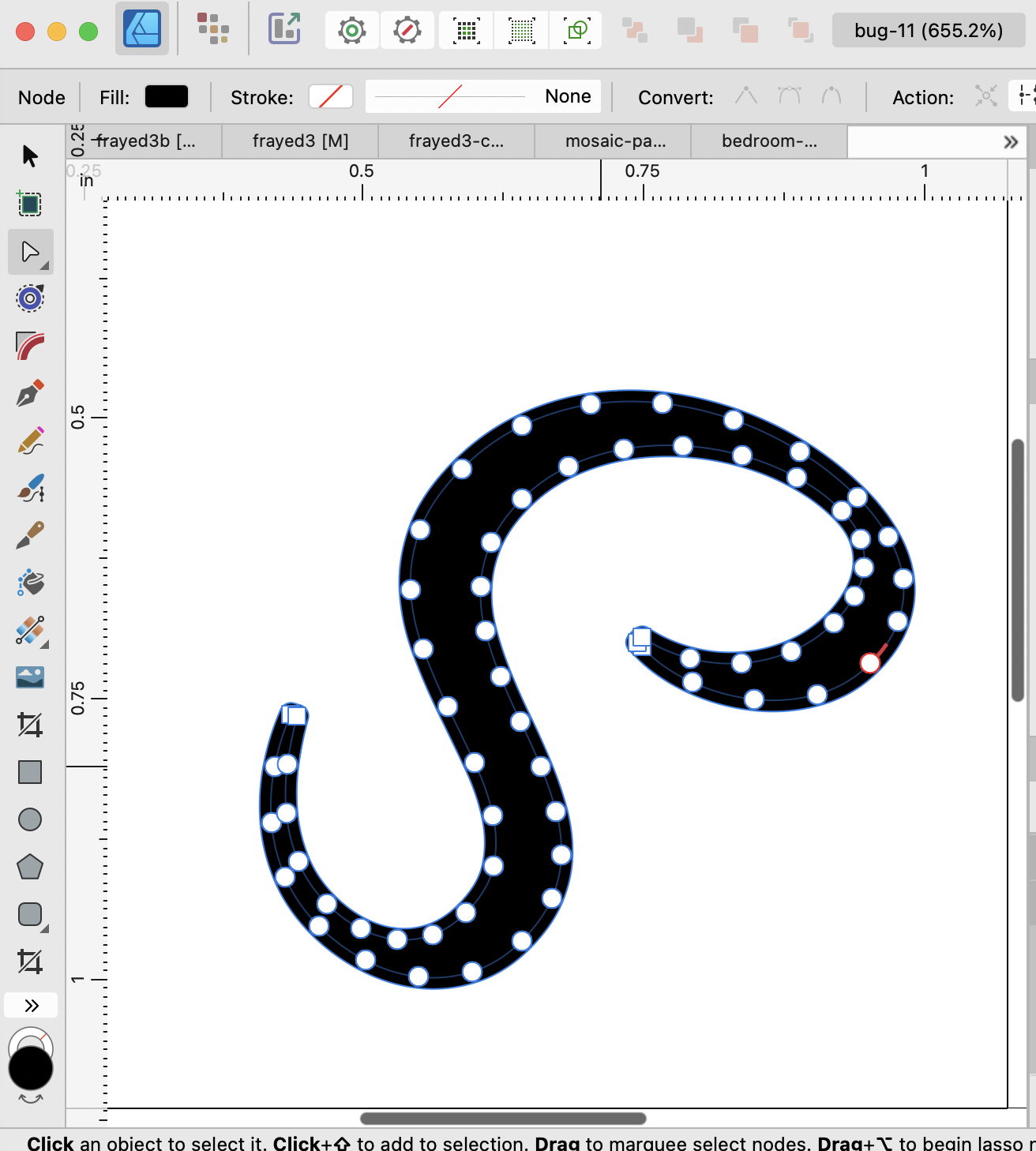
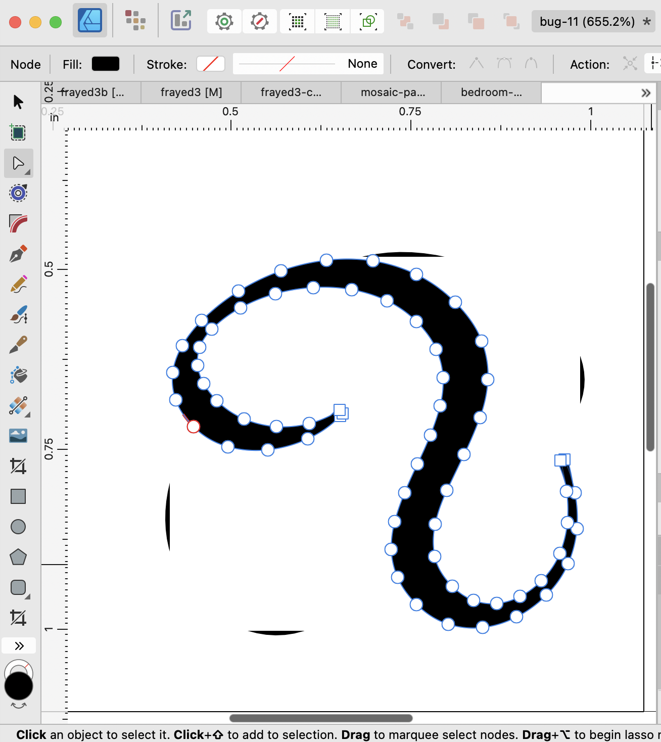
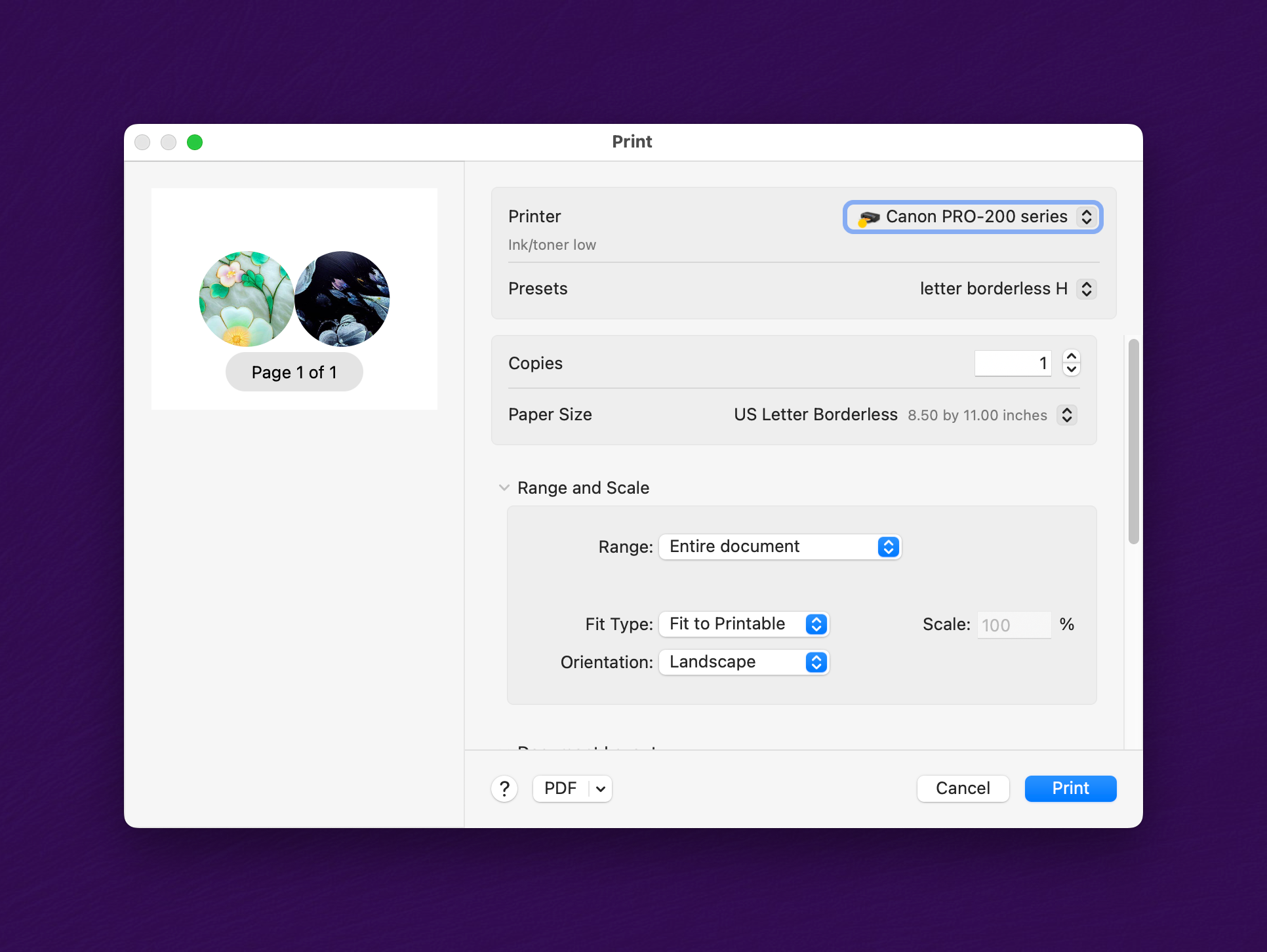
1. Open attached document. Observe that the shape has an offset applied. Choose the Node tool and select the shape. The offset is clearly visible (and correct). 2. Choose the Move tool, and select Layer > Transform > Flip Horizontal. The offset, although it still exists according to the Offset tool, has disappeared, image 2. (There are also, sometimes, rendering artifacts visible as shown.) bug-11.afdesign

-
AD2.1.1: The Contour tool sometimes produces erroneous outlines.
purplie replied to purplie's topic in V2 Bugs found on macOS
Is there a bug ID assigned to this? Thanks -
 purplie reacted to a post in a topic:
AD2.2.0 "Add" doesn't work for these shapes
purplie reacted to a post in a topic:
AD2.2.0 "Add" doesn't work for these shapes
-
AD2.2.0 "Add" doesn't work for these shapes
purplie replied to purplie's topic in V2 Bugs found on macOS
I see, thank you. -
Summary: If you try to "add" the two objects in the attached file, the second object is simply deleted. Application: Affinity Designer 2.2.0 OS: MacOS 13.5 Reproducible: Yes. Open attached file. Select the two objects. Click the "Add" button in the toolbar. Notes: If you first add a fill color to the second object, then it works. bug-10.afdesign
-
purplie reacted to a post in a topic:
AD2.1.1 "Select object when intersects with selection marquee" option doesn't work if there is an adjustment
-
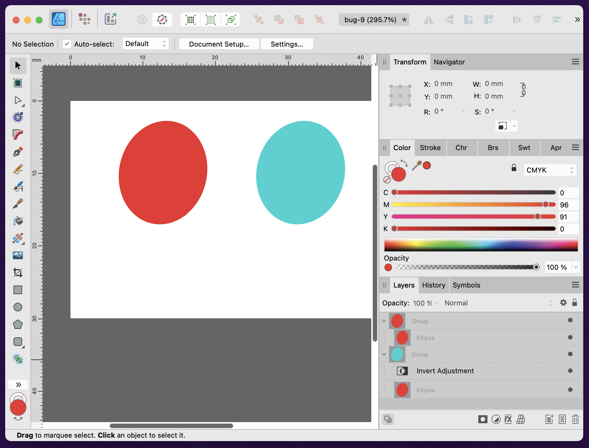
Let me rephrase it a little; I apologize that in my original post, I was unclear on the distinction between groups and objects. Set the Auto-select option to either "default" or "groups". Enable the "Select object when intersects with selection marquee" preference. If you pull the marquee completely around the two groups, then both groups get selected. But if you pull the marquee partially across the two groups, only one group gets selected, which is incorrect. (Re the Auto-select discussion, note that both objects are in the same situation, being inside groups. Therefore the two should behave the same, regardless of the Auto-select setting --- either both groups should get selected, or both ovals get selected, or nothing gets selected. It shouldn't be possible for one to get selected and not the other, if the selection marquee intersects both.)
-
purplie reacted to a post in a topic:
AD2.1.1 "Select object when intersects with selection marquee" option doesn't work if there is an adjustment
-
purplie reacted to a post in a topic:
AD2.1.1 "Select object when intersects with selection marquee" option doesn't work if there is an adjustment
-
Interesting, thanks. I wasn't aware of that option. But, per the manual, the "default" Auto-select option is supposed to select anything (both groups and objects), so I'd still say it's a bug.
-
Summary: If you drag the selection marquee halfway over the object in the attached file, the "Select object when intersects with selection marquee" option isn't working for an object to which an adjustment has been applied. Application: Affinity Designer 2.1.1 OS: MacOS 13.5 Reproducible: Yes. Steps to reproduce: 1. Go to Settings > Tools, and enable the "Select object when intersects with selection marquee" option. 2. Open the attached file. It contains two red ovals; the second oval has an "Invert" adjustment which makes it blue. 2. Using the Select tool, drag the selection marquee halfway over the two ovals. Only the first oval gets selected. bug-9.afdesign
-
purplie reacted to a post in a topic:
AD2.1.1: Export preset is not honored if pressing Enter
-
purplie reacted to a post in a topic:
AD2.1.1 Vector path is unnecessarily rasterized on SVG export
-
Summary: A simple vector object (not an image) gets rasterized by SVG export, if its opacity is not 100%, even though SVG supports setting opacity. Affinity Designer 1 didn't have this problem. Application: Affinity Designer 2.1.1 OS: MacOS 13.5 Reproducible: Yes. Steps to reproduce: 1. Create a new document, with default options for "Press Ready / Letter". 2. Use the Pen tool to draw a simple shape such as a triangle. 3. Set the shape's fill color to any color. In the Layers panel, set the object's opacity to 50%. 4. Try to Export to SVG, using any of the default preset options. Observe that the shape gets rasterized. Notes: 1. If I don't set the object's opacity, it works fine. 1. If in the Export dialog I change the option "Rasterize: unsupported features" to "Rasterize: nothing", then it works as expected: the shape is exported as a non-rasterized vector shape. But what can be happening here? How can setting the opacity be an "unsupported feature"? 2. If I try to open the attached example file in Affinity Designer 1, I get the message "Failed to open document ... The file includes features from a later version of Affinity" --- even though all the features I used did exist in Affinity Designer 1. bug-8.afdesign
-
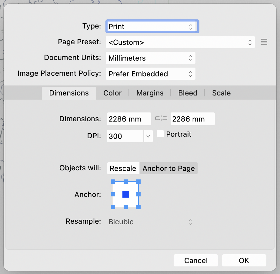
Summary: In Export to SVG, if you use Enter to submit the form instead of using the mouse to click the button, the Preset settings are not used, and the Preset is cleared next time. Application: Affinity Designer 2.1.1 OS: MacOS 13.5 Reproducible: Yes. Steps to reproduce: 1. Create a new document, and in Document Setup, make it as shown (note the resolution is 300dpi). 2. Go to File > Export. Create a Preset for Export to SVG, named "Glowforge", as shown in the screenshot. (Note particularly that "Use DPI: 96" is set, and the "Raster DPI" field is not set.) 3. Select the "Glowforge" preset. Click the "Export" button with the mouse, and export the file. 4. Go again to File > Export. Observe that the "Glowforge" preset is the default, because it was the most recently used. 5. Observe that the cursor is in the Raster DPI field, which is blank. (I don't know whether this is important.) 6. Hit Enter (don't use the mouse to click Export) and export the file. 7. Result: for me, this results in a file exported at the wrong scale (300dpi instead of 96dpi). 8. Go again to File > Export. Observe that the "Glowforge" preset is not the default. (Normally the previously-used preset is the default. Notes: I can see the result in the file's svg tag; the width and height are affected: (A) Correct result, from step 3 (clicking "Export" with the mouse) <svg width="8640px" height="8640px" ...> (B) Incorrect result, from step 6 (hitting Enter) <svg width="27000px" height="27000px" ... >
-
purplie reacted to a post in a topic:
AD2.1.1: Scale transform incorrectly computed in presence of viewBox
-
purplie reacted to a post in a topic:
AD2.1.1: Bug in Layer > Arrange > Move Inside
-
purplie reacted to a post in a topic:
AD2.1.1: Bug in Layer > Arrange > Move Inside
-
AD2.1.1: Bug in Layer > Arrange > Move Inside
purplie replied to purplie's topic in V2 Bugs found on macOS
Sorry, here is the missing attachment. I don't see the bug all the time; there may be something in this particular file triggering it. bug-7.afdesign -
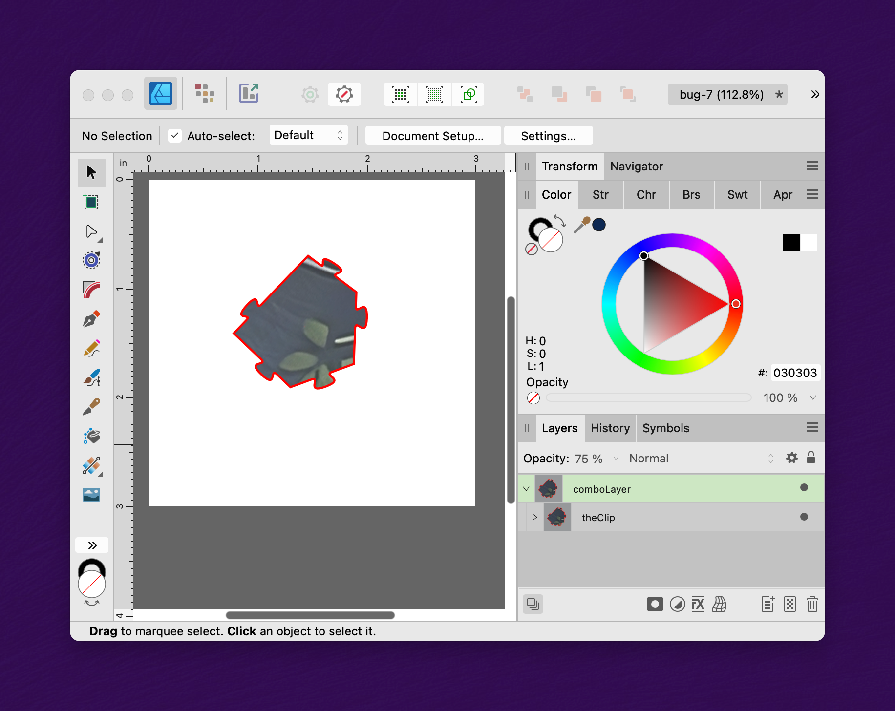
Summary: The object to be clipped unexpectedly moves when using Layer > Arrange > Move Inside (instead of using "Paste Inside", or dragging the object onto the clipping path in the Layers panel). Application: Affinity Designer 2.1.1 OS: MacOS 13.5 Reproducible: Yes. Detail: Open the attached .afdesign file. You see an image and a clip path. The task is to apply the clip path to the image. Either of the following procedures gives the correct result: A. (Works.) Select "theImage"; then "Cut"; then select "theClip", then "Paste Inside". B. (Works.) In the Layers panel, drag "theImage" onto "theClip". The correct outcome looks like this: However, the following procedure gives an incorrect result: C. (Doesn't work.) Select "theImage"; then "Layer > Arrange > Move Inside". As you can see in the screenshot below, "theImage" has moved inside "theClip" according to the Layers panel; but notice that the X/Y coordinates of the image have inexplicably moved, so that it no longer is within the bounds of "theClip". Additional notes: 1. The manual says that the action of "Arrange > Move Inside" is that it "moves the object inside the object above it on the Layers panel". That's a typo; it actually moves the object inside the object below it. 2. If you first move the image and clip path outside the layer, then it works as expected. 3. The reason I wish to use method (C) instead of methods (A) or (B) is that it's more suited for scripting with an external macro utility. Thanks for your consideration. bug-7.afdesign
-
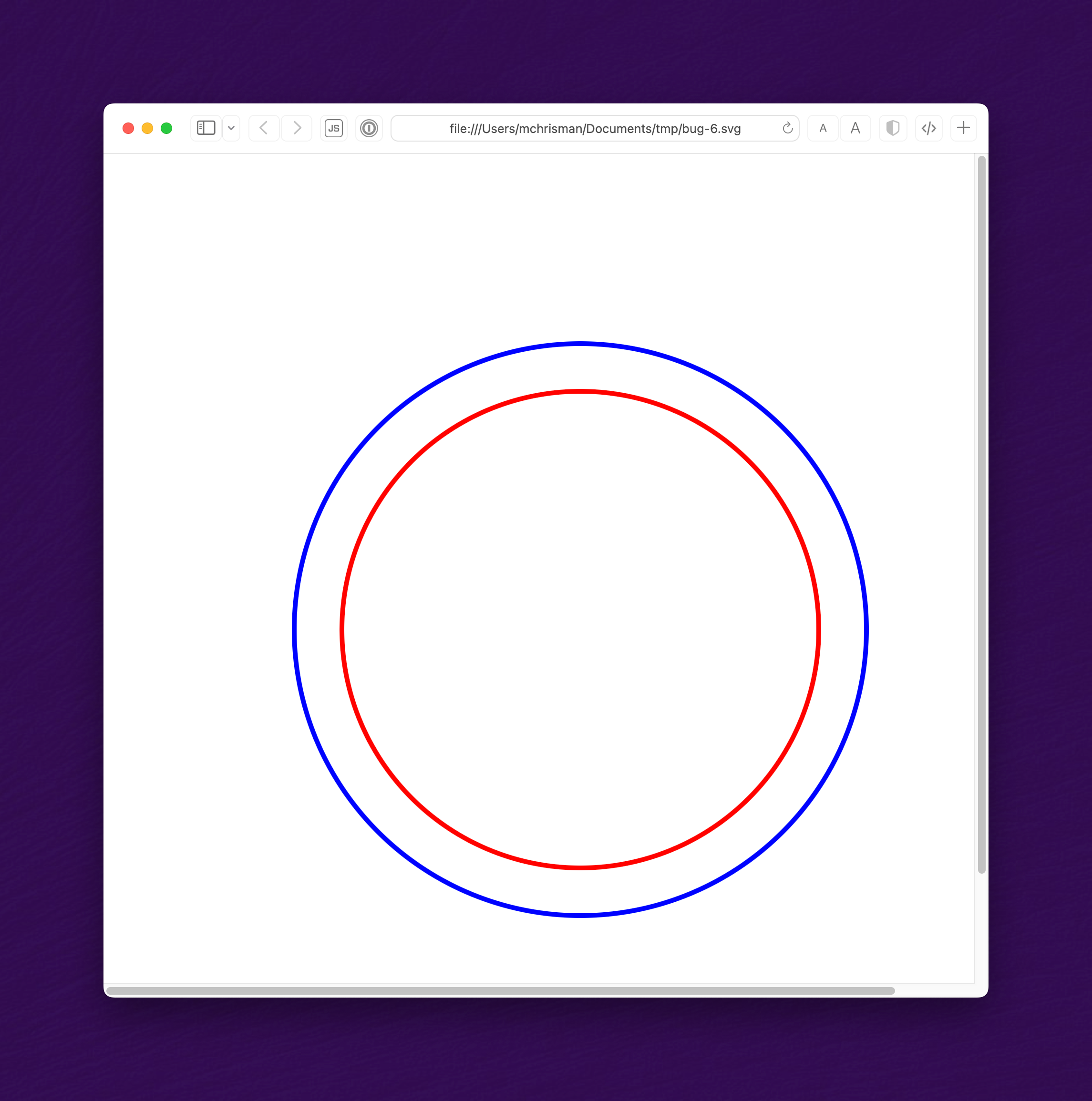
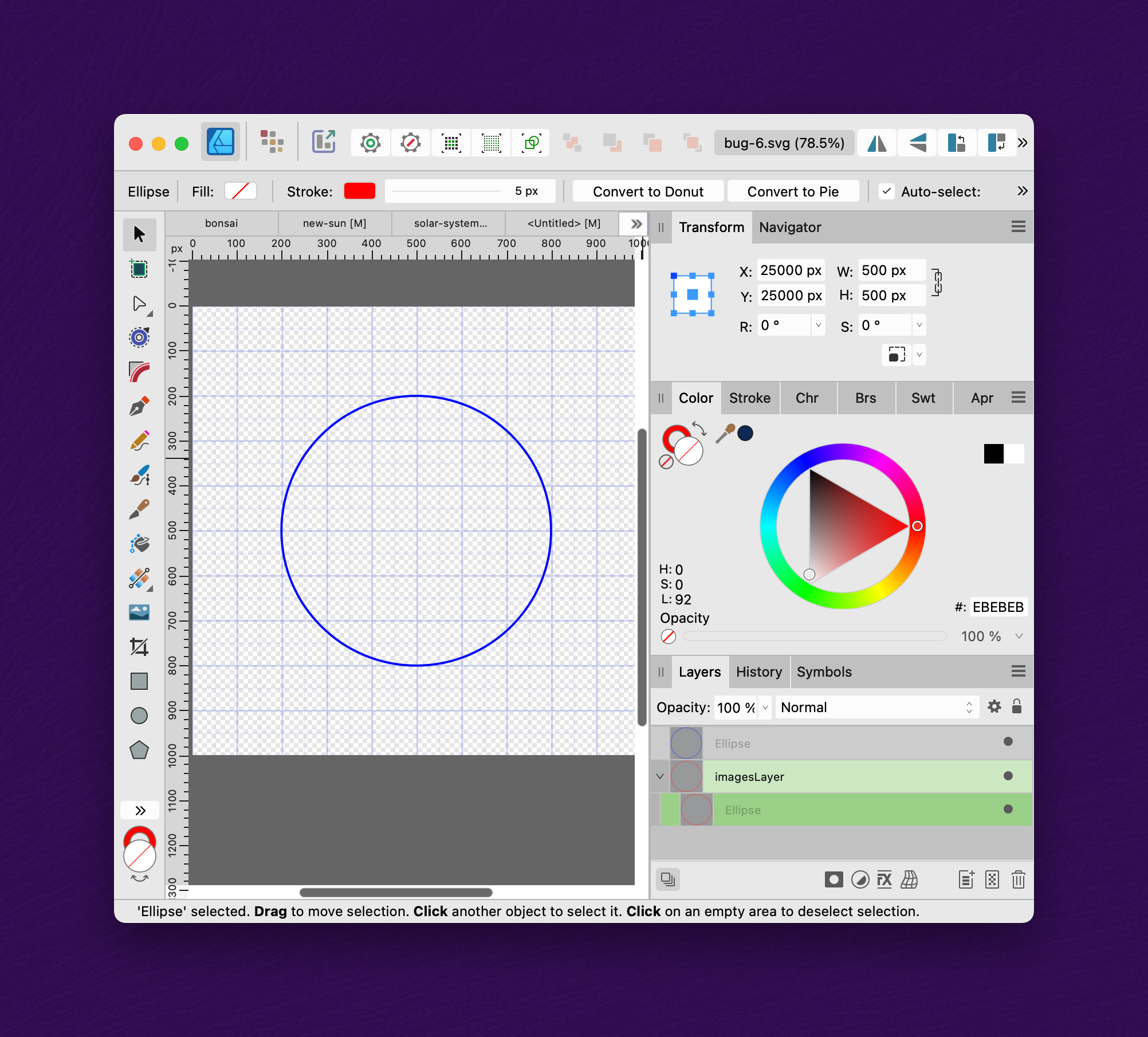
Summary: An SVG file containing a group element with a simple "scale" transform causes a shape to be incorrectly placed. The bug may be related to incorrectly using a coordinate system based on the viewBox. Application: Affinity Designer 2.1.1 OS: MacOS 13.5 Reproducible: Yes. Detail: The attached SVG file describes two concentric circles, centered at (0,0), one red and the other blue. The file renders correctly in Inkscape, Safari, Chrome, and Intellij, thus: But when opened in Affinity Designer, the blue circle is centered at (500,500) while the red circle is centered at (25000, 25000): If the viewBox is deleted from the SVG file, the result is then correct. I suspect that the "transform" is being applied relative to the corner of the viewBox; but that is incorrect. Transforms apply in the "user coordinate system", not the viewBox coordinate system. Here's a wild guess: perhaps, in an effort to avoid showing unsightly negative coordinates in the UI, AD incorrectly handles the case of the viewBox having negative coordinates: it simply added a "translate(+500,+500)", and the scale() transform got applied after that. But as you can see, that would be incorrect behavior. bug-6.svg
-
purplie reacted to a post in a topic:
AD2.1.1: Contour tool applied to clip path gives correct result on screen, but is ignored by Print and Export
-
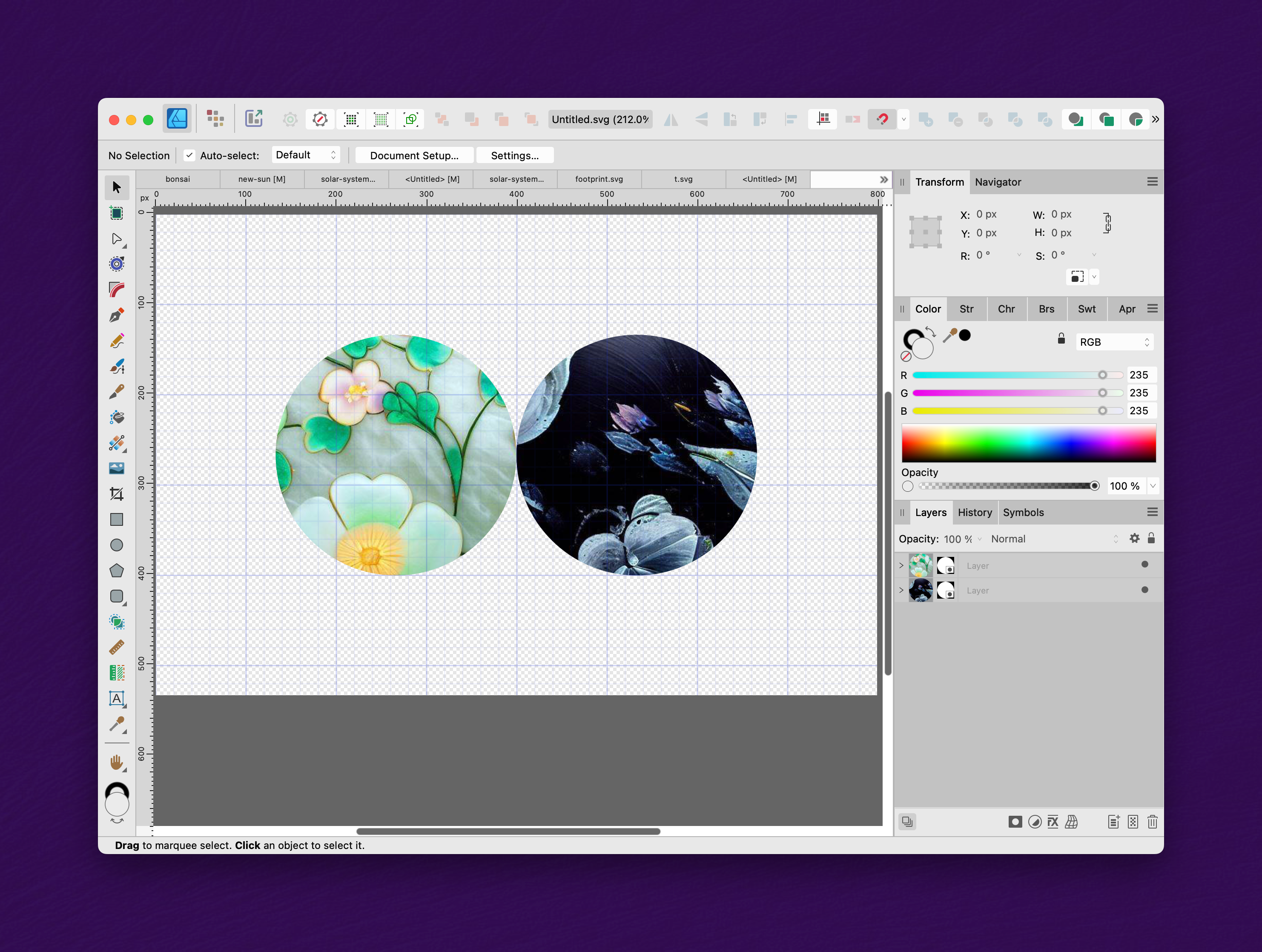
Summary: When editing a SVG file that contains a clip path, applying the Contour tool to the clip path produces the expected result on screen, but is ignored by Print and Export. Application: Affinity Designer 2.1.1 OS: MacOS 13.5 Reproducible: Yes. Steps to reproduce: 1. Open the attached SVG file. It contains two images clipped to shapes (circles, in this simplified example). It looks like this: 2. In the Layers panel, select the clip paths (the circles, not the images). Then use the Contour tool to expand the clip paths (circles) by 50 pixels. The result is correct on the screen: 3. Try to Print the file, or Export to SVG. Observe that the changes to the clip paths were ignored: Notes: 1. For simplicity, this example uses simple circles for the clip path. My real use case involves applying the Contour tool to more complicated shapes. So the "workaround" of increasing the size of the circles, rather than using the Contour tool, would not suffice. 2. I observe the same result if the clipped object is a simple colored rectangle instead of an image. 3. In Affinity Designer, there are apparently two ways to represent a clip path. The first is to create a clip by using "Paste Inside". This results in the clipped object being "inside" the clip path in the Layers panel. The second is to open an existing SVG file with a clip path. This results in a different structure in the Layers panel, as exemplified above. The bug only impacts the latter representation. I don't know why AD uses different representations for the two cases. 4. For some reason, when I open this file in Affinity Designer, the document is 800 pixels wide instead of the expected 300 pixels. I think that's a completely unrelated problem. I can reproduce this bug using a similar document which opens at the correct size. Thanks for listening. Untitled.svg
-
 Old Bruce reacted to a post in a topic:
Stroke thickness
Old Bruce reacted to a post in a topic:
Stroke thickness
-
Aammppaa reacted to a post in a topic:
Stroke thickness
-
Amy Choue reacted to a post in a topic:
(Beginner): what are good and free fonts to use for body text? Tips for licensing? Where to buy, etc.?
-
This trick might work for you, if you want the same percentage increase on all the different strokes. Suppose you want to increase the strokes by a factor of 2.5 (250%). "Select All" In the "Stroke" panel, select the "scale with object" option. In the "Transform" panel, make sure the aspect ratio is locked, and type *2.5 into the width field, and press Enter. This should (temporarily) transform everything's size by a factor of 2.5. In the "Stroke" panel, deselect the "scale with object" option. In the "Transform" panel, type /2.5 into the width field, and press enter. This should put everything back to its original size, leaving the strokes at the larger width.
-
I usually find good free fonts at https://fonts.google.com.