

lacerto
-
Posts
5,784 -
Joined
Posts posted by lacerto
-
-
I did an exercise with redefining PANTONE spot color swatch assignments as global RGB swatches, and also making all non-swatch based RGB assignments global, It is not too bad. Part of the colored objects can be selected with Select Same command, but many objects with gradient fills need to be handled one by one. The design is not very complex though, so perfectly doable. But compared to simplicity of the same job in Illustrator, one badly misses the ability to switch between spot and process and automatic creation of global (linked) color swatches just by selecting the design and adding its colors to the Swatches palette.
IceHound Marketing 2021_globalized_rgb.afdesign
Here is also an sRGB and CMYK (PDF/X-1a:2003) export of the design, showing clearly the degree of desaturation, but the exact tone of the purple/violet color cannot be reproduced accurately even in standard PANTONE spot colors (using e.g. PANTONE Purple would exaggerate the effect) so this is pretty much best that can be achieved without special inks and experimenting mixing special inks and process colors (e.g. by shading with black).
IceHound Marketing 2021_rgb_globalized_rgb.pdf
IceHound Marketing 2021_rgb_globalized_cmyk.pdf
BTW: After having had a closer look on the original AI file (which possibly was not opened completely correctly since I have CS6 and the design was created in a later version), the only PANTONE spot color that was effectively used was PANTONE 2995 U, which is a kind of cyan that cannot be printed in basic process colors. The spot black could basically be replaced with standard process black. The purple in the lower edge defined in RGB (which would effectively convert to C and M) could be produced reasonably well with process colors but in the current design it mixes partially with a gradient composed of 2995 U which makes the lower part more violet than purple (reddishness that shows in RGB is lost). But the job appears to be really designed to be printed with just one PANTONE ink (2995 U), while the presence of Purple and Cyan as spot inks do not have practical effect. But to get the reddishness, a mix of process cyan and magenta does a better job than using PANTONE inks. But if reproducing the bright cyan is important, the logo should be redefined so that the RGB global is replaced with PANTONE 2995 U, and the RGB black with which the blue creates a gradient, with K-black or PANTONE black, that is: with a a black that is produced in one ink only).
- firstdefence and IceHound
-
 2
2
-
1 hour ago, firstdefence said:
Thanks for that info
You're welcome. However I need to correct myself: global colors are not imported, it is just that spot colors, which are imported, are automatically also global, but there is no link to tints (children) so it is pretty much useless.
-
7 minutes ago, firstdefence said:
There is no fast route to this unfortunately and it doesn't appear Affinity can maintain any spot colours or global colour assignments from an Ai file
Yes, it can, both, it just does not automatically create swatches, and you need a swatch assignment to maintain global behavior of a color (but spot colors will export as spot colors):

-
47 minutes ago, IceHound said:
Can you give me the steos on how to "convert all PANTONE spot colors to RGB process", please?
It is not basically necessary to do that since if you open the design in RGB mode and export to RGB digital mode, it does not matter if there are spot colors amongst color definitions. You can also uncheck "Honor spot colors" when you export to automatically convert the spot inks to process colors.
But if you want to change the color definitions in the design and still have Illustrator, the easiest way to do so is double clicking the four spot swatches and simply just change their status from spot to process (and RGB or Lab).
This shows all color definitions that you have in the design:
and here is an .afdesign file where all spot colors have been converted to process RGB:
IceHound Marketing 2021_rgb.afdesign
If you would like to do the same in Affinity apps, you would create all four Pantone swatches and their RGB equivalent swatches and then create objects with PANTONE swatch fills and outlines and use Select > Select Same > Fill Color (and again for Stroke Color) and assign the found objects the equivalent RGB swatches.
-
23 hours ago, firstdefence said:
I'm not sure this is the designers fault in using this choice of Pantone 2995 U and RGB Hex colours would like to know why this was used
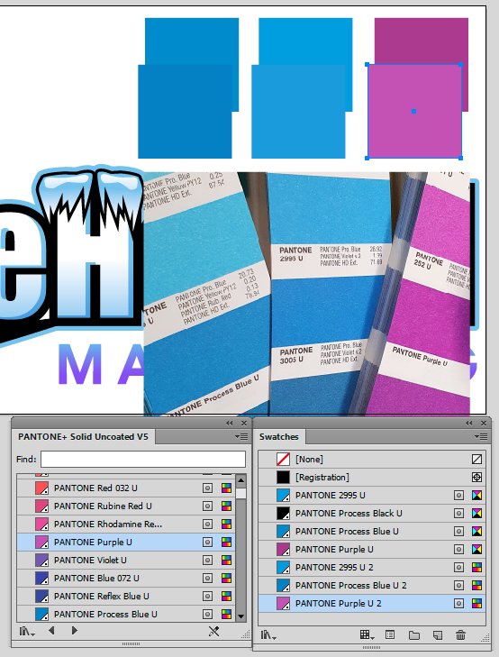
I think that PANTONE Solid Uncoated has been used as a "nice" palette, just to pick colors. There does not seem to be much point in mixing inks and process colors in gradients. In addition to that, RGB color mode has been used in design and spot colors chosen from a palette that is targeted for uncoated print stock, and to further complicate the mix, the PANTONE library used was a legacy palette with CMYK definitions, rather than with Lab definitions. Just for the reference, here is a comparison (the upper row shows the original swatches using CMYK-based PANTONE library, and lower row the current Lab-based swatches, below them a photo that I took from an actual printed color guide:
So color accuracy, as regards matching the colors with PANTONE system, has not been the primary interest of the designer, but because the logo has been created in RGB color mode, brightness of e.g. purple is certainly intentional, and that will desaturate in most CMYK color spaces when printed in process colors. Therefore I would keep the logo in RGB color space and just convert all PANTONE spot colors to RGB process (that is easiest to do in Illustrator), and just export to whatever CMYK color space needed. In some circumstances a hint of purple would show on paper, but most of the time it would come pretty desaturated. If PANTONE Purple is really wanted the logo design should be fixed so that gradients are correctly defined in PANTONE Purple (tints towards white) without process color steps.
-
Sorry, I did not realize that you did not have Publisher. You can then use any vector shape as a clipping object and make it basically behave as if it were a Picture Frame, though to scale and position the contained image you would need to use the Layer panel to select the image layer, and might need to toggle the Lock Children option on the context toolbar to achieve what you want,
I also realized that you can use the Fill tool to position and resize an image that has directly been converted to curves and then shaped with Boolean operations (which causes the placed PPI to be changed to one of the document DPI, and typically being enlargened within its containing object) so even if you cannot e.g. see image meta data (like its PPI etc.), you can still resize and reposition the image within its containing object, and manipulate the container object as you wish. The original image quality is also retained.
-
Sorry for not being able to be less confusing: the concept of (Image) and (Pixel) layers are a bit non-intuitive in Affinity apps, but fundamental. I was trying to show ways to encapsulate an image layer (e.g. a photo placed in a Publisher document) within a vector object so that you can perform Boolean operations like interchange on the encompassing vector object rather then on the image layer itself, and without using workarounds that cause rasterization of the shaped photo.
One alternative would also be converting a placed image layer into a Picture Frame layer (Layer > Convert to Picture Frame) and then shaping that (similarly as was done on the video, though there an external photo is placed into an already created Picture Frame) -- and if wanted, convert the resulting Curve layer back to a Picture Frame for easier positioning and resizing of the contained image. This way you would also avoid the kinds of sizing issues that you would typically experience when converting image layers directly to curves (and then performing Boolean operations on the curved image). Converting an image layer to a Picture Frame would reset the PPI (effective pixel per inch value) to the document DPI value (e.g. 300 ppi), but you could easily resize the image within the frame by using the scale control. That is, you can manipulate the frame in any way and yet maintain the control of the contained image size and location, because the image stays encapsulated within the frame.
Whichever way you encapsulate the image layer, the point is that its pixel information stays unchanged so you work non-destructively, without deteriorating the image quality.
-
You can work with an image in non-destructive way, not changing its original resolution, and use Boolean operations (like subtract or intersect) on the encompassing curve (shape). If you convert the curve to a Picture Frame, you can move and resize the contained image easily -- you can do so without using a Picture Frame by using a curve object for masking or clip masking, but then need to toggle the child-parent lock to have similar functionality.
Try to avoid working with pixel layers, or converting images directly into curves, or turning pixel layers to images (using the menu command, or using the Clipboard trick) just to get the ability to shape a photo or other picture type. Note, too, that you can first create the framing shape by using any vector tools available, and once ready to place a contained image convert the object first to a Picture Frame and then just drag the image content into the Picture Frame (you can drag images directly from the file system or Stock Panel, or drag images within the document or Layers panel into a Picture Frame control in the Layers panel).
-
-
You can use the Style Picker Tool (instead of the Color Picker Tool or Color Picker of the Color panel), to pick (copy) the original (untranslated) color definition of another object to be applied to selected object(s), but that would copy all attributes of the source object (and attributes of both fill and stroke), so not restricting just to color.
-
On 4/15/2023 at 3:16 AM, kenmcd said:
I just did a quick test in ID17 and it appears to work as expected.
I installed version 18.2.1 of InDesign and
yes, it can render these fonts without issues, so it seems that Adobe apps have been able to do so for some years now (possibly starting from late 2019 when support for variable fonts was implemented in InDesign).No, I was just sloppy when testing. There is no change from CS6 versions, it is just that if these problematic glyphs have a fill, they will be rendered correctly, not showing the overlapping outlines. If the fill is removed, they show also in the latest versions of Adobe apps (InDesign and Illustrator at least; as mentioned Photoshop handles text outlines differently and does not have this issue), both when using variable and regular fonts:
Affinity apps by default draw the stroke in front so they would show the crossing outlines also if there is a fill, but this can be changed by using the Order option of the Stroke panel.
EDIT: The behavior shown above in InDesign with filled text only works when using outside aligned stroke. If using center aligned stroke, the strokes would show similarly as in non-filled text. Affinity apps can avoid that by changing the paint order but when using other than the outside aligned stroke, the stroke width would of course be affected (e.g., half or all of the stroke would be covered by the fill color).
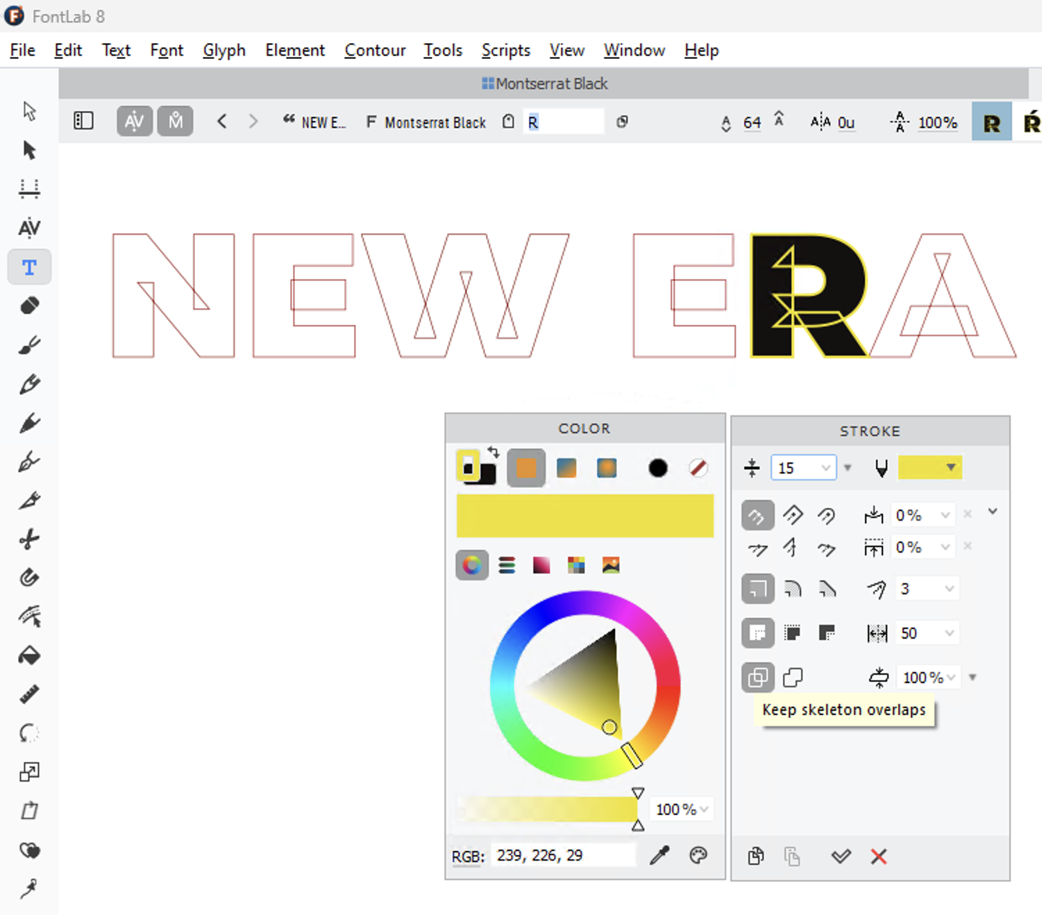
EDIT2: There is also another consideration and that is whether a graphic design app, capable of converting text to outlines, should actually (by default or at least optionally) honor the original design, using the exact construction of the glyph outlines and control points? Could the designer intentionally use crossing outlines in a way that causes an effect shown above in letter "W", and that would show also in filled letter when using center aligned strokes? Perhaps not in letter shapes but e.g. in symbols? Is there a property (meta data, instruction) that allows the designer to indicate whether such shapes are to be removed when rendering the font, or honored? So far the only app that I know that can actually remove these "artifacts" and that allows full control of stroke (width, alignment, cap and join type, etc.) is FontLab 8, and there showing or hiding them is an option called "Keep/Remove skeleton overlaps". That's an option I would like to have in graphic design apps, as well (along with the ability to choose whether outlines are drawn in front or back), but perhaps this is just something that is intended to be used in font editor? But I am not sure if "removing skeleton overlaps" should be something that a graphic design app should do automatically, without giving the user an option of keeping them, instead.
-
5 hours ago, thomaso said:
As if the Swatches panel lacks in feedback.
At least it has (or used to have) refresh issues so you might need to deselect and reselect an object, or refresh the panel to get it redrawn. The link might still exist, though. There are limitations, and possibly bugs, too, and the behavior is not properly documented, but I am just saying that these attributes are transferrable and that the described workaround does allow creation of user-defined global swatches (including spot colors), and saving of the color attributes like overprint, tint and opacity, in a way that allows using them "as if" they were application-wide palettes.
-
On 4/14/2023 at 3:51 AM, kenmcd said:
The issue is with those applications not being able to apply a stroke properly.
But which graphic design application that allows full control of glyph stroke attributes [and also conversion of text to outlines] can do that? Latest Corel, Xara, VectorStyler, Pages and Inkscape cannot, QuarkXPress 2018 cannot, nor can e.g. Illustrator or InDesign CS6 (though those two date from the time variable fonts did not exist and so such compositions were probably rare and there never was need for rendering in some specific way that removes overlapping strokes; I have currently not subscription active on those two on so cannot check if the current versions can).
Word and Photoshop can, but they do not allow similar control of outline (e.g. stroke alignment) -- the latter only via an effect. I rather switch a font than do graphic design in Word, or logo design in Photoshop. [FontLab 8 Windows version can, too, in Text preview, while the macOS version is totally buggy in rendering preview.]
On the other hand, if these kinds of overlapping compositions are required by variable fonts, then why does not Skia use / depend on them?
Basically I am just saying that Affinity apps are not alone in this alarming inability.
-
On 4/13/2023 at 8:43 PM, thomaso said:
To me in V1 the global attribute of being linked to a global swatch may get lost for objects copied between documents even if both documents got the same document palette imported. – Was this improved in V2?
I do not think so but I have not properly tested this.
It seems that 1.x and 2.x versions behave identically. I.e., if you copy an object from one Affinity document to another (even across versions), objects with a specific color definition (CMYK, RGB, spot, etc.), color attribute (overprint, global, tint, opacity), and even layer attribute (opactiy, blend mode) are copied along, and the attributes show in the Color panel and are also exported to e.g. PDF files, even if no swatches are automatically created in the receiving document's Swatches panel.
Even if the attributes and color definitions are passed through (despite the color mode and color profiles, so the values are retained, not appearance), In order to an object to behave like a global color object (e.g. serving as a parent to children and having a capability of being redefinable and pass changed values to attributed objects), it must be linked to a swatch in the receiving document's Swatches panel. If the swatch is not there but is created the link will be automatically re-established to objects with the swatch assignment and parent-child relationships are restored. This happens even when loading an external document palette with correct color definitions and attributes, and versions 1 and 2 share the palette format.
-
4 hours ago, scgreentea said:
Is it possible to have colours set to global in a system swatch? i am using AD 1.10.4 on an imac.
As a workaround, you can set any custom palette with global, spot and overprint attributes as a default for a specific color mode, to be loaded as a document palette when a new document of that color mode is created (the palette would then also autoload when the same document is subsequently edited). You can save such palettes on the disk and import them as document palettes and set as default for a specific color mode, thus overriding a possible previous default palette.
All defined attributes (spot, overprint, global, color mode) survive so the feature has some functionality of an application palette (the same palette could be made default for multiple color modes).
I think this should work similarly also in 1.x versions of Affinity apps.
-
52 minutes ago, Park_Triolo said:
Thanks for trying. I tried that as well and yes, it breaks the artwork.

Yes, sorry, should have had a closer look. And it does ruin it pretty badly. The design is so deeply structured and detailed that it is probably very time consuming to try to fix it (and though much of it does not appear to require deep nesting and isolation, some parts do, but pinpointing those exact parts may be hard, and might require help from Illustrator to properly see what was done in the original).
-
18 minutes ago, GeirSol said:
Place is passthrough if I understand right.
Is there an option when using place?The control (a dropdown listbox) for Passthrough options is shown in my screenshot above, framed in red. The shown drop-down control, visible when you have the Move Tool active and a placed PDF file selected, has options Passthrough and Interpret. The default is "Passthrough", but I think that the last used option is remembered at least for the document under processing so it is best to double check.
-
59 minutes ago, macfloer said:
I really dont understand where the problem comes from.
Yes, odd.
Try what happens with this one:
I do not have these physically installed but just activated with Adobe Fonts and used on macOS Ventura in Affinity Publisher 2.04, and they export just fine.
Could it be that you have these fonts on your system both as installed physical fonts AND activated as Adobe Fonts, and this could result in auto-conversion to outlines?
-
I thought that your source was an IDML document opened in Publisher but if you have actually opened a PDF file with embedded fonts, they would not be available for you without having the same fonts physically installed on your computer or activated with Adobe Fonts (or with Microsoft Office, or any other cloud source possibly used in the original document), and used fonts mapped correctly to installed ones.
Embedded fonts in a placed PDF would be useable and exportable only if the PDF has been placed (File > Place) to be passed through (the default option), rather than to be interpreted (which option requires installed fonts, similarly as opening a PDF) -- or if the placed content is rasterized. Adobe apps behave basically similarly, so they honor the license restrictions specified by font manufacturers for usage of embedded fonts.
What seems odd is that most of the used fonts should have been converted to outlines, since when you open a PDF with embedded fonts and matching installed fonts are not found, they are typically replaced with "equivalent" installed fonts, not converted to curves. Conversion to curves happens when you open or place EPS files with embedded fonts (whether those fonts are installed or not).
-
1 hour ago, ,,, said:
However, Move Outside seems to do the same as Release and there is a shortcut (which can be edited) for Layer > Arrange > Move Outside in Designer, a shortcut can be set for the same in Publisher, and a shortcut can be set for Arrange > Move Outside in Photo.
Nice! It would seem that Move Inside within the same group would then perform "Mask Below" operation, which can be very useful as both commands seem to be macro recordable!
-
9 hours ago, HeikeT said:
In short, what @lacertosuggests would work if you choose a text character as a divider.
I seem to have misunderstood your goal because my suggestion was more a writer's trick to create a graphic divider in context of text creation while still keeping the divider as a text element that can be replaced using e.g. text styles.
If there are no such requirements but you just search a way to replace divider markers like "***" with any graphic element that can subsequently be easily replaced within Affinity apps, I would use one of the following methods (already suggested above):
- Use a specific glyph in a regular or symbol font, along with a character and a paragraph style pair that defines the desired alignment, size and spacing (space before and after) for the break, and use Find and Replace to apply text replacement along with the style based formatting; there is no need to use "Bullet" style in this case so the used symbol would also stay searchable; note though that there are still limitations in Affinity apps as for use of color fonts (e.g. SVG color fonts are not supported); or
- Search the divider strings and replace the found instances manually one by one (i.e. via Clipboard paste) with a linked image (which could later be changed in one go by relinking to another image using Window > Resource Manager); or
- Borrow the Symbol feature from Affinity Designer (via Designer Persona) and replace found divider strings manually one by one with them. Designer Symbols can consist of any elements and can subsequently be edited so that all changes are immediately reflected in all symbol instances.
Note that linked images and Symbol objects used as inline elements move along with text when it is re-flown.
-
Whenever you place a PDF file to be passed through, all embedded fonts should show correctly in exported PDF. They basically cannot show incorrectly because the content has not been interpreted, so a replaced glyph indicates that a placed file has been placed for interpretation, or that it has been opened for editing. (EDIT: In contrast, when passing through fails, the exported file is typically rasterized, but the glyphs still show correctly rendered, even if no longer in text/vector format.)
When a PDF has been placed to be interpreted, or when a PDF is opened for editing, all fonts that the document uses, must be installed and they need to be mapped correctly. In case of having opened a PDF document for editing, you should be able to check from Window > Font Manager if this is so.
I tested clef symbols with Sibelius 7 and both passthrough and interpretation/opening work properly. If you do not have Sibelius installed on the same computer where you have Affinity apps installed, please note that Opus alone (the default Music font of Sibelius) consists of 18 styles, so make sure that all styles have been installed if you are going to open or interpret your Sibelius scores.
-
Since Interstate (total of 44 styles) and Calibri (6 styles) are both fonts that can be activated with Adobe Fonts, I would try reactivation (= deactivate and activate again) of these fonts, and for other missing ones, that they are physically installed on your computer where you have Affinity Publisher installed.
-
Thanks. Basically yes. There does not seem to be anything specific in the composition that could cause conversion of text to curves. The only thing that comes to mind is that since the document appears to be originally an InDesign created publication, most of the fonts probably having been activated with Adobe Fonts, I would try if reactivating the fonts on CC could resolve the issue, as sometimes reactivation is needed to make fonts properly available with non-Adobe software.
UPDATE: In addition, a couple of fonts, Times and Zapf Dingbats, might actually be old Type 1 PostScript fonts, which Affinity apps support only partially (and current ID versions probably not at all), so there is a chance that this explains some of the issues you have experienced with this document.


Why does my logo from Illustrator look different in Designer
in Affinity on Desktop Questions (macOS and Windows)
Posted
I had yet another look on the design, based on my comment above related to inability to reproduce properly the bright cyan of the logo. As two of the defined four spot colors, PANTONE Purple U and PANTONE Process Cyan U, were not effective (even if present as zero tints), and process Cyan and Magenta (or their equivalent RGB definidion) were used instead, I assume that what had happened in the design was that the tones of the design were originally planned to be reproduced in richer gamut PANTONE inks, especially the "icy blue" for which PANTONE 2995 U was chosen, but the purple-violet tones for which PANTONE Purple and PANTONE Process Cyan were initially selected were later replaced with standard process inks cyan and magenta (which actually produce these tones better and at least more predictably).
There were additionally a couple of other issues, probably Affinity introduced, resulting in that the black marked with PANTONE Process Black U was overprinted (also when used as 0% tint) so general overprint setting for K100 had to be disabled in export settings. Additionally there was a transparency setting used in one instance that had to be replaced with a tint to avoid rasterized objects. With these changes, and globalization of the remaining RGB definitions, the design can be reproduced pretty well on paper, and easily also modified (to adjust the violet-purple area of the design), using just one spot color (PANTONE 2995). In addition, C, M and K are used as standard inks.
IceHound Marketing 2021_reconstructed.afdesign
IceHound Marketing 2021_reconstructed_cmyk.pdf