Search the Community
Showing results for tags 'AF-291'.
Found 6 results
-
 expand strpke AfDes.mov
 -
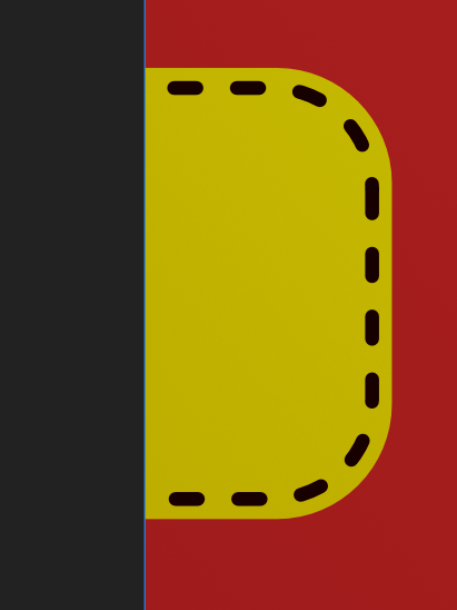
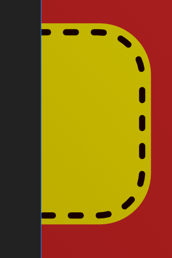
At first I thought this was related to the new phased stroke feature, but I've had this happen with that on and off. Either way, where I've used a stroke that consists of dots, the first dot in the stroke is malformed when outlined or in an exported PDF. I did not have this issue in the prior version of Designer 2.

-
I am having a problem when Expanding Stoked Paths... RPReplay_Final1687691523.mov
-
 This seems to be a regression from the retail to the beta in Designer Beta 1769
-
Example A : Seems start gets destroyed Original Expanded Example B : Seems start gets destroyed Original Expanded Example C : Seems dash line style phase will be ignored
-
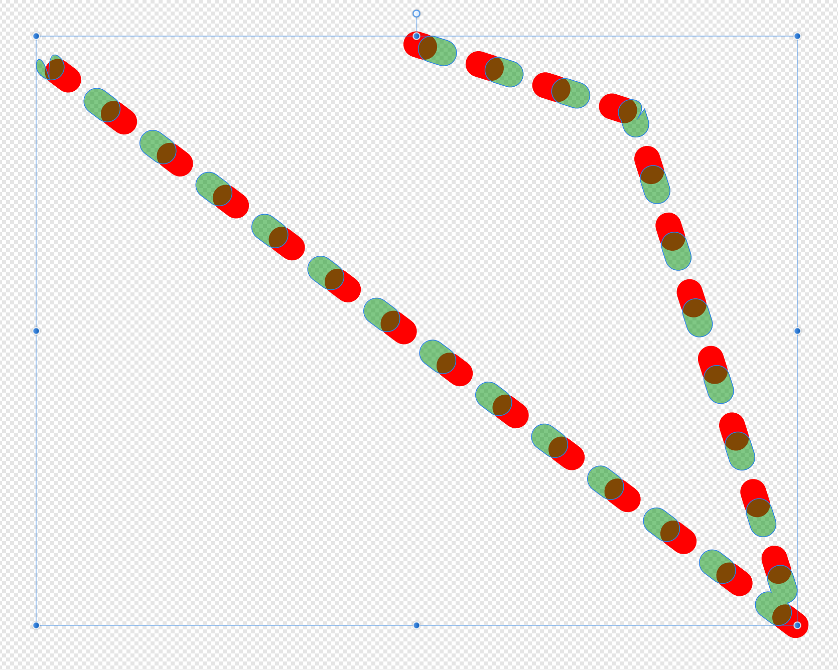
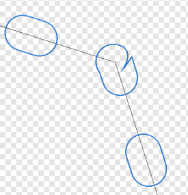
I'm working with an old design where I've (unfortunately?) used lots of dashed lines for a pattern fill. I need to convert everything to curves for this job. I'm seeing issues and as a consequence the patterns are no longer consistent across the filled areas. I can't show the actual design but here's an illustration: The red is the original vector and the green at 50% is the result after Layer | Expand Stroke has been applied. The curve has a negative phase and it looks like this gets set to zero when the expand is applied. Also notice the funky shapes top-left and the corner top-right. This is in the latest release of AD under Windows 10. Any thoughts?