

R34V3r
-
Posts
50 -
Joined
-
Last visited
Posts posted by R34V3r
-
-
9 hours ago, Sean P said:
R34V3r what PDF export settings are you using and what application are you using to view the exported PDF in? I can only see this when I open the PDF (Exported using default PDF for Print) in Chrome and zoom in.
If you inspect the original branch objects prior to export and change the fill layer to be black you will see a white outline going around them - after inspecting further it looks like the source images you've used have a very hard edged, non aliased alpha channel which I think is PDF viewers to show those objects the way they do. I've attached a screenshot of the Alpha Channel of what of those objects from the PDF export show, and also what they look like with a black shape underneath (essentially making it easier to see the non transparent areas of the image). You can see that fringe line around them that is likely causing PDF viewers to show those objects the way they do.
I don't believe its a bug within the software, just a side effect of the original source images you used and how PDF viewers render them. The best situation in this example would to just be to rasterise the group containing the Fill layer and those two branch images. This way the branches no longer have any transparency and sit on a flat background.
This changes nothing. Replacing the Fill Layer with a rectangle still shows the problem when the PDF is exported and viewed in a browser (and a little bit, but not as bad in Acrobat), despite nothing getting rasterised.

Thx for the clear explanation Sean. It does make sense now.
Maybe a dumb question, but doesn't that mean the visualization method in one of the applications is wrong, or is this such an unstandardized thing? It's just that all of the pdf viewers I tried the banding appears (non chromium edge, chrome, edge, adobe reader), but loading in the pdf back in designer shows no issue. It just triggered this fear in my mind that I have to double check every time I export now in different readers to make sure it is rendered properly, and therefore cannot rely that what I see in designer is what I get in a portable export unless the exported file is opened in designer again.
In my mind, Designer should either already show the banding when editing, or the pdf should look like the editing view (at least when you disable any compression in the export settings). Or am I talking crazy here?
Edit: it's not that I really want to look for an issue here, my OCD just triggered on this and I let it drag me down the rabbit hole
-
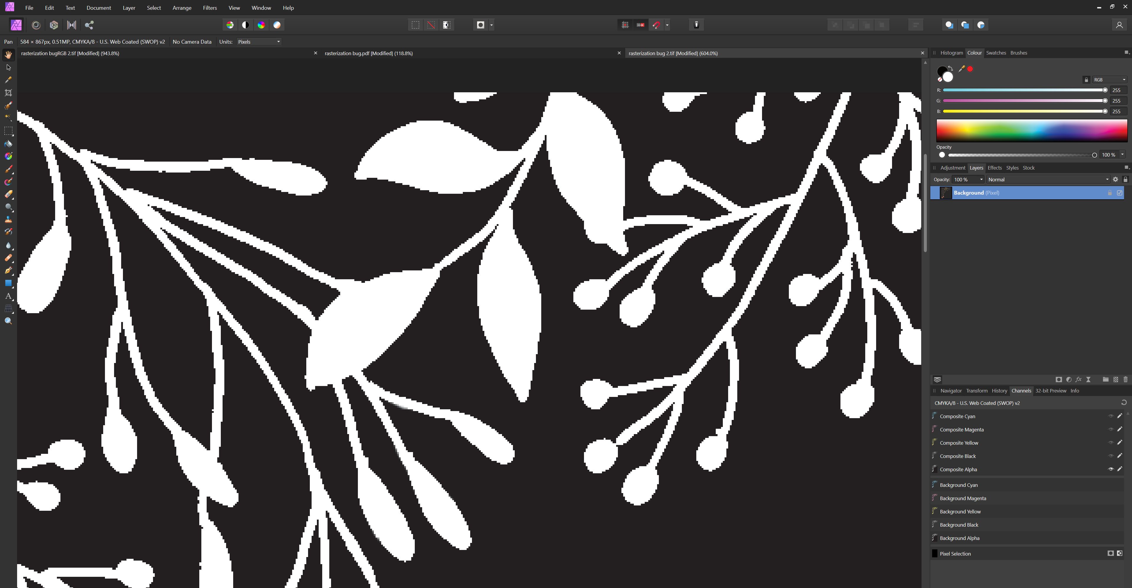
I recently did a personal project (rasterization bug.afdesign) and noticed something weird when exporting to pdf.
I got a pixel layer on top of a fill layer together with some text. The pixel layer looks fine when editing within designer:
When I export the pdf, there is a notice that designer wil rasterize some areas, which is the pixel layer on top of the fill layer. When opening the resulting pdf however, There seems to be some weird bands on the pixel layer:
Tried some different stuff, like converting the color profiles, testing different pdf configurations like not allowing jpeg compression etc.
The only preset that got me the same result as the designer view is to flatten the whole pdf, which ofcourse also flattened my text. I worked around the issue in the end by rasterizing the pixel layer together with the fill layer and export it as a normal "for print" pdf, but it made me wonder if this is some bug or expected behavior, as it felt a bit tedious to flatten my layer stack to make it rasterize the right way.Can anyone shed some light on this? Thx in advance.
-
On 12/12/2018 at 1:02 PM, Mark Ingram said:
It won't be CUDA, as that is NVIDIA only.
Is hardware acceleration planned for 1.7 like on the Mac version?
-
Hi all,
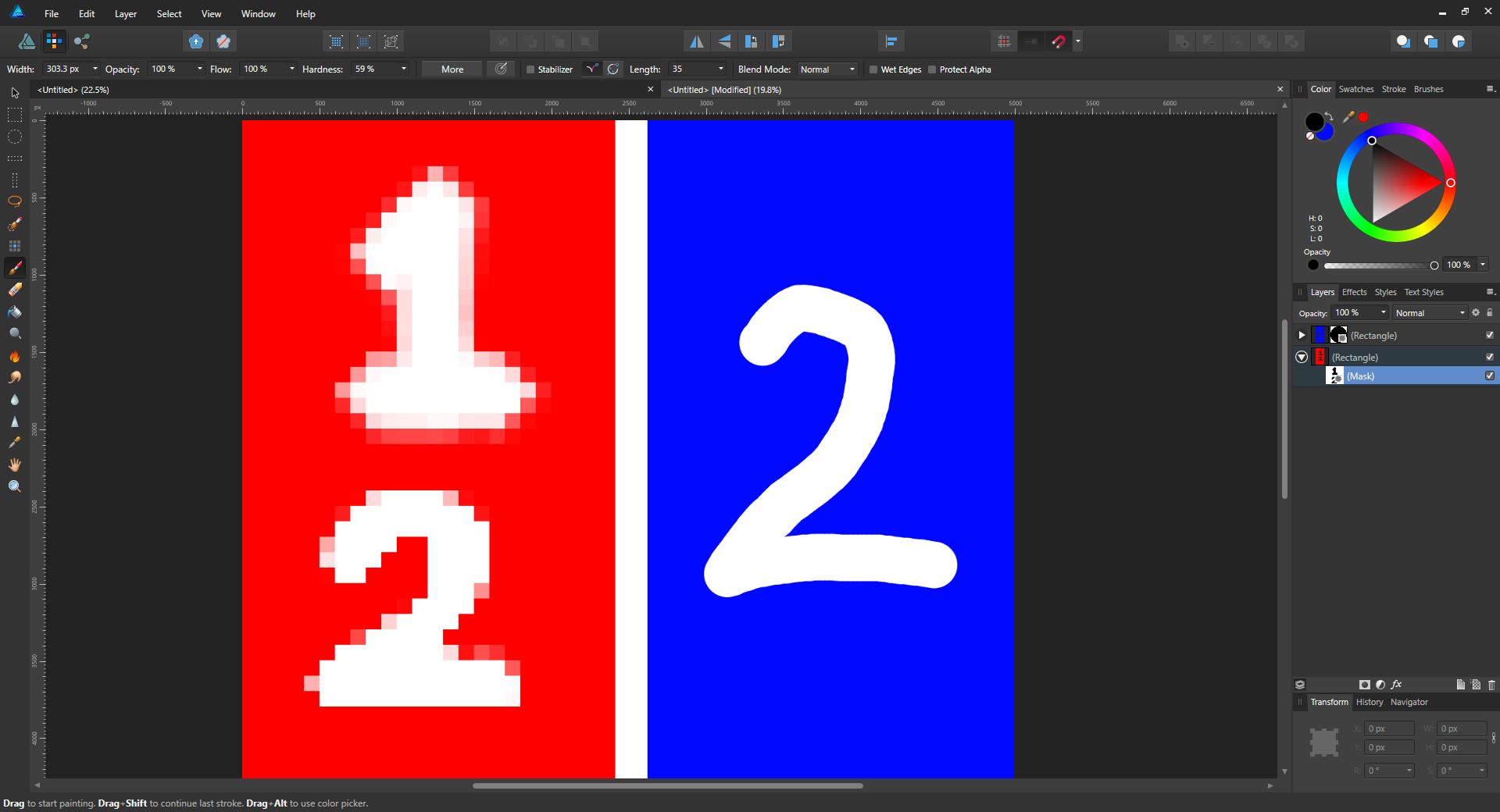
I was wondering if there is an option to scale pixels masks with the document if you increase the resolution in designer.
To illustrate, I drew 2 rectangles in a 50px/50px document. When I apply a mask to RED rectangle and paint a "1" in it using the basic round brush, you can see the pixels. scaling up the document to 5000px/5000px does not seem to scale the mask with it, as it remains pixelated. Drawing a "2" after scaling up remains in a low resolution and only if you create a mask after scaling up, like I did in the BLUE rectangle, seems to apply the document resolution to the newly created mask.
DESIGNER 1.6.3

In photo, these masks seem to scale nicely when you change the document resolution, so is there an option to get the same effect in designer?
PHOTO 1.6.3
-
On 8/26/2016 at 11:49 PM, OldDave said:
This came up because during its maiden run, Affinity Deisgner complained that my video card didn't support directx 10.
Interesting wrinkle. I'm running Affinity Designer in a virtual Windows 10 Pro machine via Microsoft's Hyper-V virtualization.
Dxdiag in the Hyper-V WIndows machine reports only a directx 9e. The host's dxdiag tells me (as I knew) that my graphic card is running directx 11.2. (The host also has a Windows 10 Pro installation).
Hyper-V apparently substitutes its own virtual hardware - it apparently can't see into my host machine's innards and find the physical card.
A web search results in a possible solution, to use RDP, something about which I know nothing and won't try to play with. Unfortunately, it doesn't seem to be a sure fix.
This may not trigger much instant action among the Affinity developers... I don't know what percent of your user base is working on a virtual machine. But lots of us who dabble in beta releases DO use virtualization as a way of sequestering any rogue behaviors.
Hyper-V does not virtualize your gpu by default.
you have to enable remoteFX, which is basicly API passthrough from your VM to your dedicated gpu (intel graphics wont work here though). It allows you to "virtualize" your GPU.
It should support directX 10 and 11. The limitation though, if I'm not mistaken, is you can only create virtual gpus up to 3GB VRAM. Performance is also a bit of a mixed bag and only directX applications are supported (so no openGL or Vulcan).
If you want to use gpu accelerated programs, vmware has more options, including pci-passthrough so you can use a gpu in your vm as it was directly plugged in without a hypervisor (though for this you need a supported CPU (with VT-D or AMD-V))
-
-
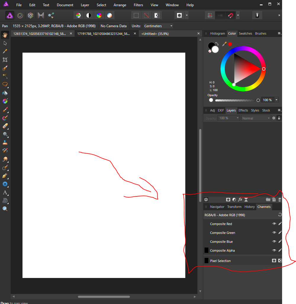
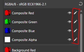
are all your channels editable? the pencil icon in the Channels panel below right should be active on all channels:
try ctrl+D or cmd+D to make sure you dont have a selection active.
try rasterizing the layer again, i've had some problems in the past where the layer was shown as a pixel layer but acted as an image layer
-
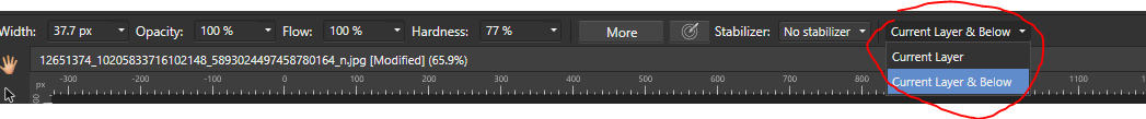
workaround maybe, what if you create a layer above the one you try to inpaint, and set you inpainting to current layer & Below:
-
3 hours ago, MEB said:
The Equations filter outputs a pixel layer - the text will not be editable anymore. For rasterised results you can also use the Mesh Warp Tool which offers visual control over the distortion.
Unfortunately it's not possible create this type of distortions keeping the text editable or as vectors no matter the program used (unless you edit the nodes of the letters manually).
Thanks for the reply.
The mesh warp is indeed a great way to do this. If I get this right, it rasterizes the layer first before warping it, so enlarging certain areas does mean you have some degree of sharpness loss in the output.
Are there any plans to make a vector flavor of this tool in designer?
-
This is literally the best title I could come up with. I would like to shape my text like this:
So starting small at the start, enlarging it to the middle and going back to small at the end.
Is this possible without destroying the text layer into a curves group? Or what might be the most efficient way to do this in affinity designer?
-
this is probably a minor feature that takes a lot of time to implement, but here it is.
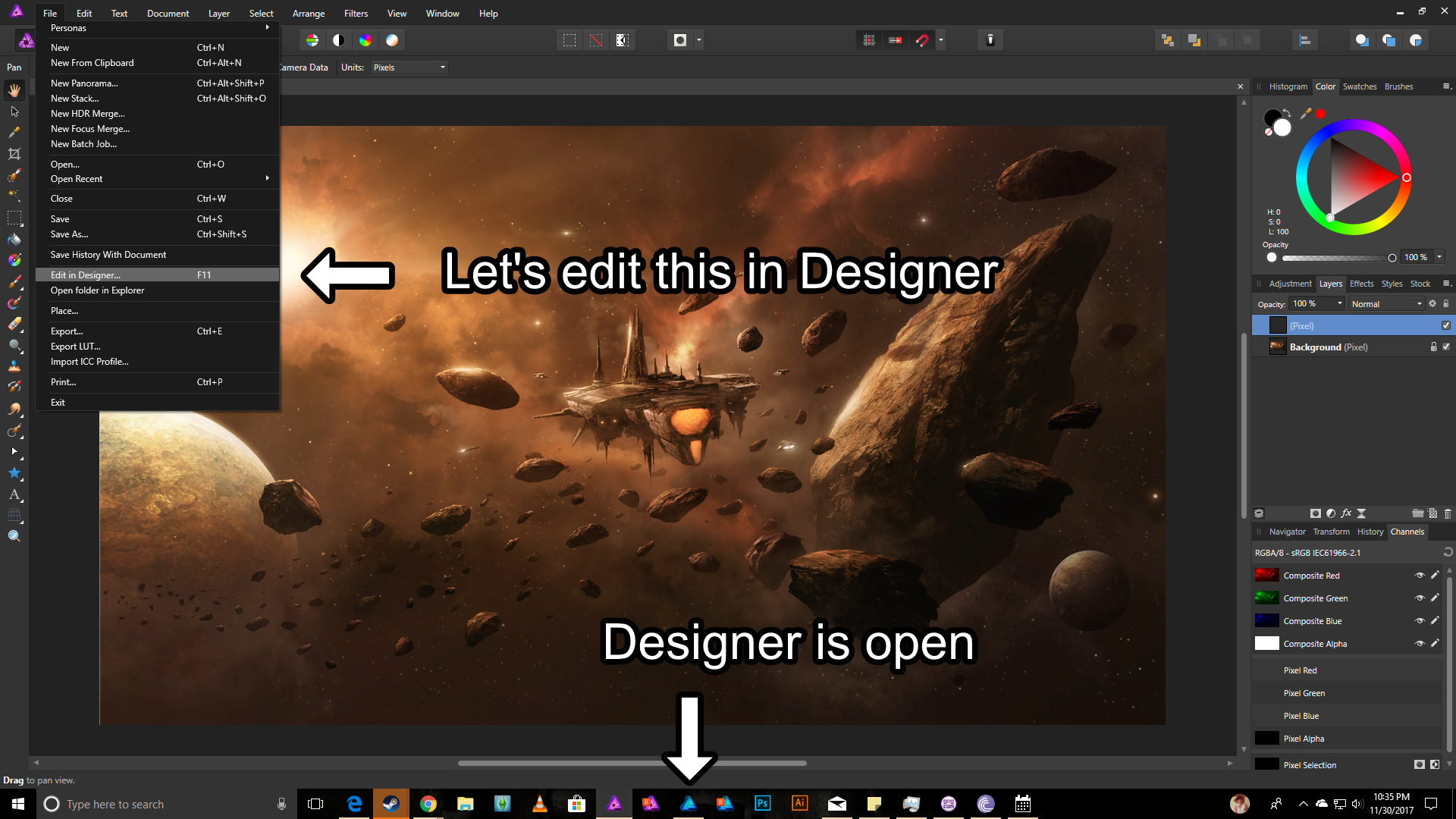
I love the "Edit in Photo/Designer" option under File, but in Windows 10, this doesn't make the other app active when the program is already launched.
Can this be changed so Windows switches automatically to the other application?
-
Custom wet edges is there, but I cant seem move any nodes on the graph, I also can't choose one of the preset graphs sometimes.
-
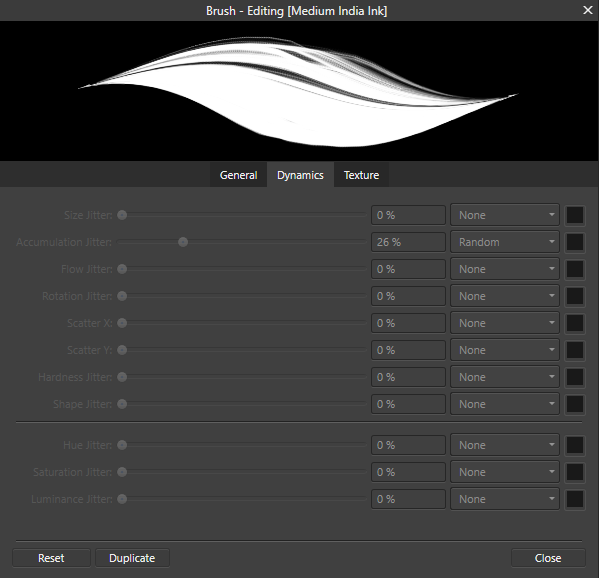
since 1.6 I also seem to have a weird issue with my brushes where the dynamics settings are all set to 0, and if you change the value the whole dialog grays out. this happens almost always with the DAUB pro brushes that were in the pre order pack.
-
nvm, overlooked it
-
how does one access this magical feature in 1.6? I can't seem to find it
-
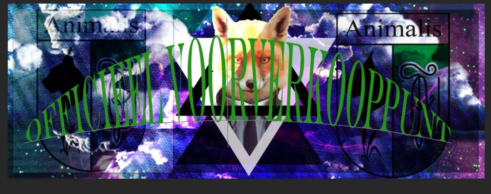
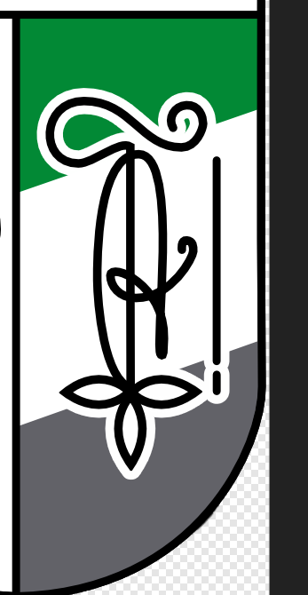
I don't know is this is already a thing, but I came across the following problem when designing a logo:
the logo has a part that looks like this:
As the background of the shield is always white, I fixed this by grouping the black curves and applied a white outline to it.
the problem is that this will rasterize when exporting to a vector format like svg or eps. So I wanted to counter this by creating a substract compound with the green and grey shape beneath it.
I tried to select the group and expand it using Layer -> expand curve, but that didn't do much.
I solved it by manually copying the curves, enlarge them to the right size, expand each curve as creating compounds will not take curve thickness into account, and then create the compound.The problem I encountered then is the fact that enlarging the curve thickness is not always the same as outlining, so I had to manually transform some points to match the outline.
Is expanding a group of curves with an outline a feature in designer? Or is it on the horizon? It would save a lot of times to solve problems like this.
-
On 8/26/2017 at 4:51 PM, MEB said:
Hi HagensWatch,
Welcome to Affinity Forums
You can perform math operations in the input fields already. Check this help topic for details.
Are there any plans to let the calculations you make in input fields parse in realtime like it is on the mac version right now?
I loved how in the affinity photo tutorials, the calculation in for example the equations filter is done while typing it in, and I noticed you have to unfocus the field in Windows in order for it to parse.
-
-
awesome,
loading EPS files causes a crash though,
I did not have that issue in the .80 beta -
Can the < select -> select sampled color > feature have an add and substract option like the other selection tools? I really like this feature but it would be a lot more usefull if you could expand the selection with other picked colors
-
-
Is there an integration with Windows 10's tablet mode in the works?
Like a switch to an Ipad like UI when someone flips the keyboard on a device like a surface pro?
I always felt the desktop UI not that user friendly for such devices and was really impressed with the UI on the Ipad version.
-
I mainly like to work on a surface for photo editing thanks to the great screen, pen input and touchscreen. I think a lot of people also like surface as a photo editing machine.
After seeing the Ipad version of Affinity photo it left me a bit wanting of the traditional desktop UI on devices like the surface however. It is a great UI experience when using the device in laptop/desktop mode, but when you want the paint with the pen for example, the experience turns bad quickly. I allready struggled with the fact that touch input is seen as the same as a mouse click instead of panning the canvas, so using the touchscreen as a main navigation tool is not that intuïtive, but after seeing the Ipad version, a lot more things pop out to me like "damn that's a good idea, I wish my surface could do that".
I was wondering if Windows 10's tablet mode could be more integrated with the application, like switching to the Ipads UI when tablet mode is activated, so that editing on a device like the surface is a lot more comfortable. This would mean that someone could just flip the keyboard and work in the document with a UI tailored for tablets, and flip it back to tablet mode when wants a more desktop like experience.
Are there plans to implement such features into the desktop app? Or is there a touch based UWP app in the works?
I was really blown away in how good the Ipad UI actually is, and I really think a more integrated experience into Windows' built in tablet mode will help a lot of people in their workflow.
-
are there any plans to support text on path for PSD files when you set the option to Import PSD text as text rather than bitmap?


Filter layer clipping not working
in V2 Bugs found on macOS
Posted
Hi, not sure if this is a bug or if I am doing something wrong, but I was recently playing around with a mockup for a UI design and noticed some weird behaviour in a live filter layer.
File included, I wanted blur effect on the top bar of my design, so I created a live gaussian blur layer and clipped it to a rectangle.
The blur seems to apply as expected in that area, but it looks like some parts of the layers underneath blur as well on the out-of-clipping-mask area (you can see the shadows and background of each card item getting blurred out despite being out of the clipping mask area).
I assume this is a bug?
UI design bug.afphoto