TerraD
-
Posts
13 -
Joined
-
Last visited
-
 Thank you very much for you nice support! Excellent work! I slightly adjusted one of the claws (added 2 'sharp' nodes), but it really looks nearly identical as before! Obviously you know a lot more than me regarding AI and CorelDraw and understood the concept easily! In particular I do not understand what has happened with the huge DCT letters - those used to be 3 objects D C T before and are an outline and 2 segments now. Was this needed in order to be able to make white transparent? While I love that we can print this now, I hate at the same time that I still have no idea how to redo this next time I stumble about a similar problem.... This was exactly the reason I decided years ago for Serif Draw and upgraded later to Affinity Design. I think if you are not using Illustrator or CorelDRAW every day they are far to complicated to be mastered...
 -
 TerraD reacted to a post in a topic:
How to create a transparent mask for one color
TerraD reacted to a post in a topic:
How to create a transparent mask for one color
-
I think you describe this excellently. I hoped there would be a way to simply create a mask with everything that is white and than set this part to transparent. Background is already transparent. Yep, that is exactly what I'm looking for. Tried to find information on how to create that mask and how to make the graphics transparent there, but did not find anything in the help nor in the forum - I suppose there is just too much information to find the correct hint :-). Due to how this was designed in AI I think masks will work better... Hmmm, good question. I usually send them the correct PDF. I'll check on that. Anyway, I think I should master the treatment of such a mask anyway for the future!
-
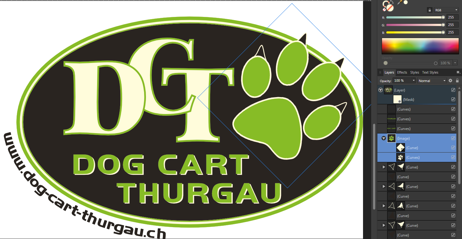
Hi Thank you for your support. Yep, I think this part is an image - but I do not understand your remark concerning the clipping mask. Actually I think I could easily redraw the image part in Affinity designer, so that it would consist of curves only. I did not do this, as I did not see how this would be an advantage to solve my basic problem described above. Concerning the white: I have no idea where this is coming from: I only have that problem in Affinity (all tools) and in PDF-X-Change editor. First I thought this to be a feature, but I think it is not! I assume there must be some color profile (in my Windows-System???)) that only gets applied by those programs. Tried to find a solution but never found one. Both programs have the wrong color not only on the screen, but when printing as well. However when I export to PNG or PDF colors seem to be correct. It's annoying but up to now I was able to live with that.... DCT mit Text ai.afdesign
-
I have a preexisting Logo in 3 colors on transparent background. I imported it from a .eps ceated bei AI. This logo should be printed in two colors only (on a white bag). Means I have to convert everything that is white to transparent. Can anyone direct me to tutorial on how to create a Mask with all white colored areas and make that transparent? Simply changing the color white to transparent will not do, as this will simply bring the black behind it to display.... Not sure it that matters: Most of the logo consists of curves, but there seems to be one part that is an image (selected on the attached screenshot).However the image part seems not to be rasterized - all colors are solid.

-
 TerraD reacted to a post in a topic:
Problem to close curves
TerraD reacted to a post in a topic:
Problem to close curves
-
Problem to close curves
TerraD replied to TerraD's topic in Pre-V2 Archive of Desktop Questions (macOS and Windows)
Thank you! A very good hint. I did not knew it¨! Affinity's UI is always a bit complicated for me. I suppose this is due to the fact I have no Illustrator knowledge. Suppose it would help to know a professional illustration or photo manipulation tool in order to understand all that beautiful functions! I only do this as a hobby and always had great respect during the last 20 years of people mastering tools like Illustrator and PS. But when Serif stopped Draw I realized I would need to take the step to some professional tool... I do not regret that, but it takes me now often clearly longer and causes me to curse more to create a distinguishable better result.... :-) -
TerraD reacted to a post in a topic:
Problem to close curves
-
Problem to close curves
TerraD replied to TerraD's topic in Pre-V2 Archive of Desktop Questions (macOS and Windows)
Thank you for the explanation! Well done - I was able to join my curve as I had wanted to do! One Segment was a curve the other a combination of curves. I divided it and had additionally (I think not mentioned in your text) to break up segments 1..2 and 3..4. Then I was able to join them as wanted! I left the rotten file in place, so that I can redo this process a few times until I can handle such situations with perfection! The most valuable hint (I tediously created a copy of the dog outline last night, as the project needed to be done by today - so that problem was solved for my project anyway) was probably your FYI - because now I know how I can avoid the problem in future! Thank you for this support! -
Problem to close curves
TerraD replied to TerraD's topic in Pre-V2 Archive of Desktop Questions (macOS and Windows)
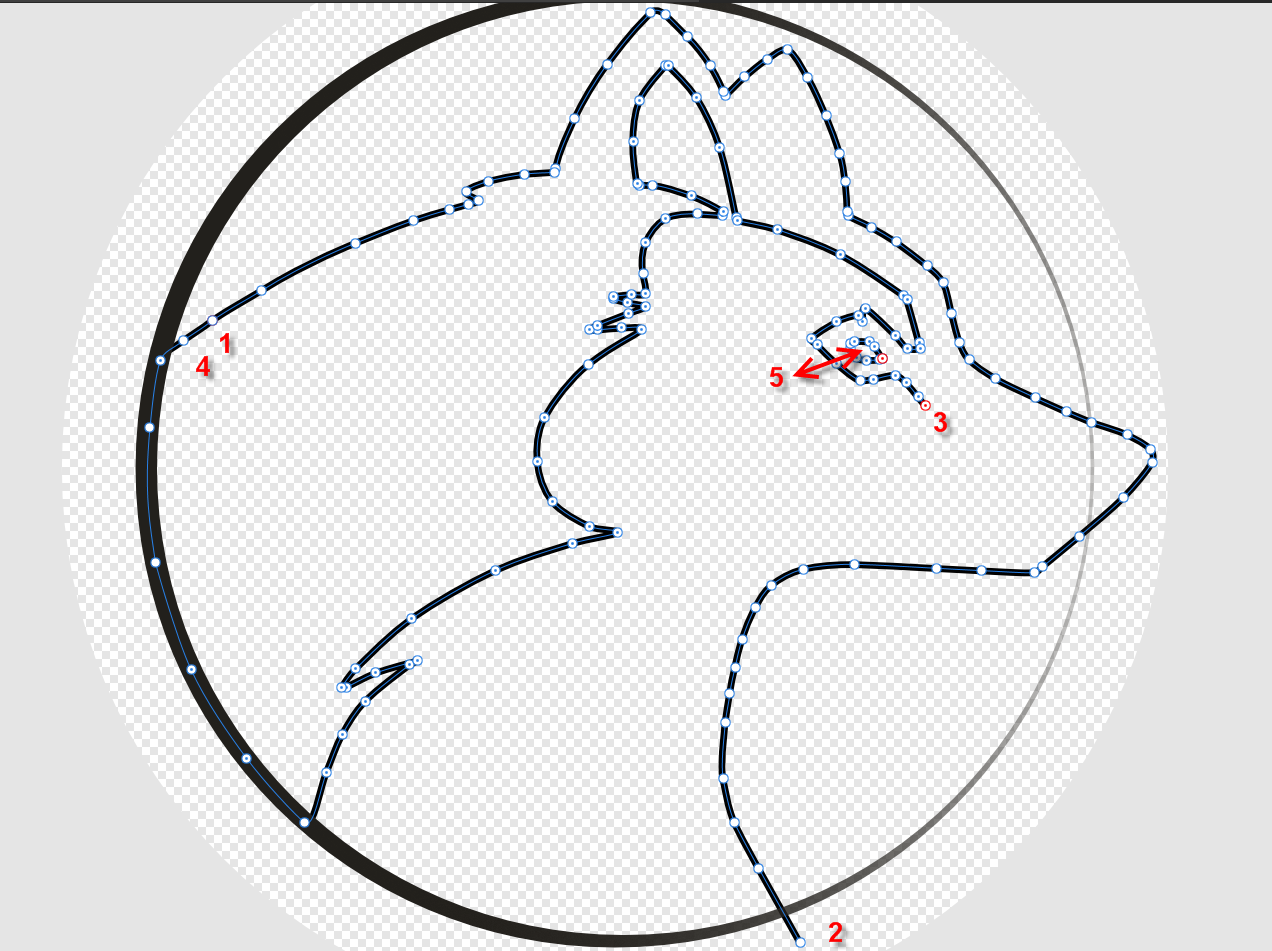
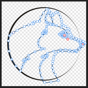
To make the process more clear that led to the problem: I started drawing at point 1 and drew my curve till 2. There I broke (without intent) the curve and was not able to attach to the same curve again. So the curve 2 to 3 is in an own segment. This segment broke again in point 3. I have no idea what I did then - but 3t o 4 is in the _same curve as 1 to 2_! When I arrived at 4 I tried to join it to 1 in order to get a closed curve. Those two however did not join correctly - they are still 2 different points. I then proceeded to the eye (5) and this is in the same curve too. However: This time the joining of start and end worked - this is a shape (closed curve). The breathing hole in the nose is an own curve again. This too is a shape (closed curve). My main problem is, that I need to color that image... And this will not work the way it is now...
-
Problem to close curves
TerraD replied to TerraD's topic in Pre-V2 Archive of Desktop Questions (macOS and Windows)
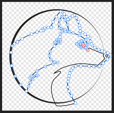
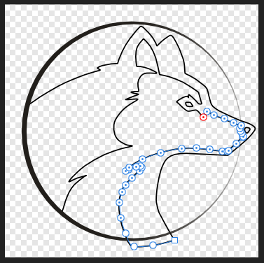
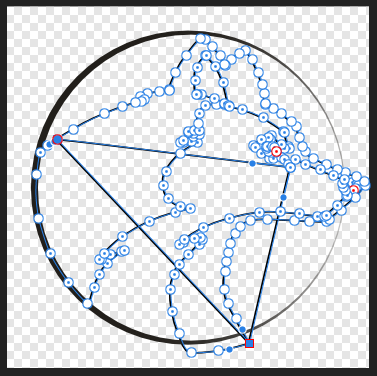
That is what I did. But this leads -depending on the selection I start with - either to the above sample image 3 or 5. Means: There are 2 or 3 additional connections that connect the curve segments! I tried to cut them out or to remove the last point of the curve-segments. Nothing helped! I tried reverse curve' as well - did not help either! It looks like Affinity does not join adjacent end-points of the curves but the distant ones... -
I drew this image and now I can not close the curves. It got broken during the design. As soon as I try to close them I get additional lines, connecting the segments. Any way to salvage my work?
-
How to name an Outline
TerraD replied to TerraD's topic in Pre-V2 Archive of Desktop Questions (macOS and Windows)
That will work. However it is always a bit dangerous that you forget to 'unhide' when you do the final output. If possible I prefer fail-safe solution. If it does not get exported to the .PDF I would use a linewidth if 0.1. As I said, hardly visible if you zoom in a lot... -
How to name an Outline
TerraD replied to TerraD's topic in Pre-V2 Archive of Desktop Questions (macOS and Windows)
Not sure about this: Is it possible to reduce the line width even to 0.0 instead of 0.1? With 0.1 you will see (and print) a very fine magenta outline when you proof your design (well, I know 0.1 wan't be visible in the final printout. So it only disturbs during the design). When the line width is set to 0.0, the line will not be visible at all. I think this is preferable. Is it? - I have not enough experience with this... However: Right now I have no idea if a line of width 0.0 will be exported to the .PDF - and that is mandatory in order to cut the contour later... -
dutchshader reacted to a post in a topic:
How to name an Outline
-
Alfred reacted to a post in a topic:
How to name an Outline
-
How to name an Outline
TerraD replied to TerraD's topic in Pre-V2 Archive of Desktop Questions (macOS and Windows)
Hmm, I understand: Layer -> Layer Effects... -> Outline does not create a line, but an area (check this by reducing the opacity of a single vector object to 1% (not 0%)). You will see the area of the object in magenta. To do it correct: Select all objects and create a Copy. Without clearing the selection use 'Joining objects' and execute 'Add'. This will result in a vectorized outline. Now change Fill to none and Stroke to 'magenta', line width '0.1'. The resulting object will have the name of the lowest object in the above selection (you will have 2 objects of this name now). So change the name of the newly created object to 'cutkontur'. -
I have a freeformat logo (vector-based) and will produce a sticker from this. The producer of the sticker demands me to add an outline in 100% magenta and name that outline 'cutkontur' . The sticker will be cut along this line. I used Layer -> Layer Effects... -> Outline to add the outline. This works perfect, but I see no way on how to add a name to the outline. How can I name that outline? Affinity Designer 1.6.5.135, Win7 Enterprise x64