EkDor
-
Posts
6 -
Joined
-
Last visited
-
 Sean P reacted to a post in a topic:
BETA Designer v2 DXF & DWG Export Issue
Sean P reacted to a post in a topic:
BETA Designer v2 DXF & DWG Export Issue
-
@Sean Ok I took a look and read of file and article. I had the layer setting set incorrectly in the export. As long as we Keep relevant objects in Named layers we should be able to direct CNC operator sufficiently. Thanks for your assistance.
-
Sorry for the delay. It's been too hot to be in my studio. I'll go through and follow this up. Thanks for the responses so far.
-
BETA Designer v2 DXF & DWG Export Issue. These do not export the groups or layer names. If it's possible, can we have this. The exports use generic naming and separates all consolidated vectors into separate layers and lumps all of it into the same layer. When sending a file to a CNC operator it can be helpful to be able to give them some direction as to what operations are meant for each vector. Thanks for your time.
-
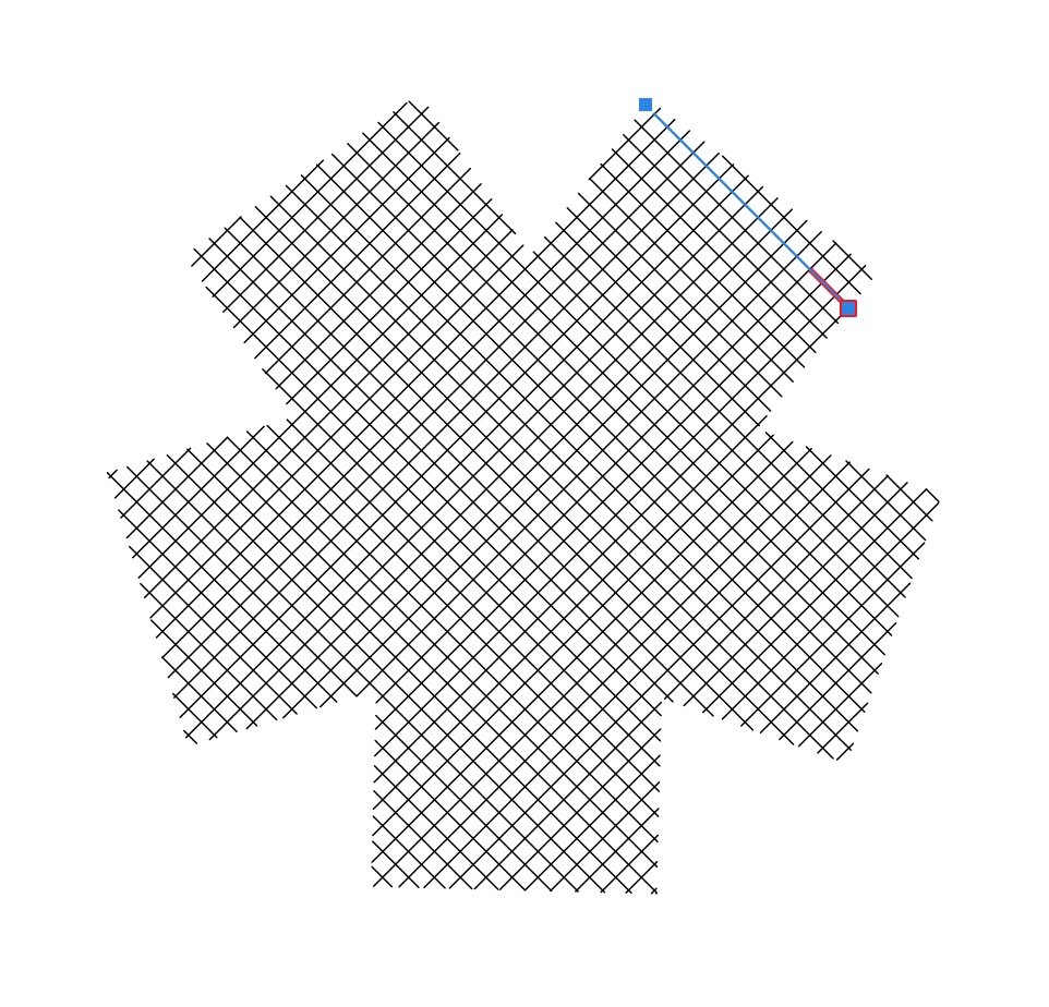
I would find it helpful and I think it would be a good addition in general to have a live Cross-Hatch shape. Or better a fill that is vectored into just straight lines. So to try an describe it: I would select a closed vector shape that I want to have a vectored cross-hatch within. Then select the cross-hatch tool for it. Then adjust values in the settings for it; such as distance between lines, angle of lines, whether to do a 90 degree equivalent second layer (optional). This would create a series of parallel vector lines that are not joined that fill the area of the originally selected closed vector shape. I guess this would remain attached to the original shape so lone as it's still live (not baked). Or treat it similar to the Vector Fill tool. Baking it should have option to keep or not keep the original shape at the edge. This is important as some operations with CNC machines might not want to the edge line as part of the same operation. Attached image showing example.

-
Designer 2 Some thoughts
EkDor replied to EkDor's topic in Feedback for the Affinity V2 Suite of Products
Oh great thank you. I have forwarded this to my father... vader -
First love your software and recommended it to my dad who bought it. I have some feature requests, suggestions, thoughts etc. By giving these I am in no way implying I know better or dislike etc. My father uses steel laser cutting services who only accept DWG and DXF files. I have helped him with his workflow to convert through an online service, such as Convertio, by exporting as SVG then converted to DXF and then send onto the cutting company. This is annoying to him. Would it be possible to add DWG (or DXF, I think DWG would be more appropriate you). There is an issue of work flow when opening an SVG and the Document Settings default to crazy settings. Perhaps a custom config for that would make it quicker to set it correctly. For example; we both predominantly use mm, because we output to the real world most of the time, so I would export to SVG. If for some reason I have to open that SVG in Designer 2 I will get a document in px, and ppi is 72, and need 96 ppi, and the document dimensions are incorrect. I am unsure how well you can help with this since I know that, at least in part, the issue is caused by SVG standard. Would we have a dimensioning tool. Would be good to have it function like guides do with it’s manager etc. But have them output as vectors or raster depending what people are doing. The ruler tool works fine as a mechanism, but it doesn’t stay and there is only one. A combination of the Ruler tool and Guides would work great to dimension with.