Bassthang
-
Posts
42 -
Joined
-
Last visited
-
 No idea. All I did was select the brush tool. I didn't go as far as choosing a brush. (I don't think I have EVER done that yet!) So I have to assume that it's using the default settings, as when installed. (This has only been installed a few weeks, as I've just moved over to a new Win11 PC.) But if I do the exact same thing in 2.6.2. It's fine. Now it could be that something had affected the brush type since it was installed, but I have no idea what. I mostly use Photo for retouching pencilled originals and so my needs are simple. If I had messed around with brush settings, I certainly hadn't done it recently, and I think the brush tool was working fine a few days ago (I was doing more of the retouching I was trying to do when the problem came up), so something other than user error is indicated, unless it's some hot-key combination that I've accidentally triggered. I've just uninstalled the 2.6.0 version, so as to not to accidentally use it again. I should have done some more detective work first, but when I could only find the 2.6.2 installation location from the shortcuts, I looked in the app settings (which still didn't tell me the location - thanks, Microsoft. . .) and when I saw the option to uninstall it from there, I took it without thinking about doing more tests. If I get time, I'll re-install 2.6.0 to a known location and do some more tests. Thanks for your help, though!
 -
Yes! There's the answer: I have two installations now: one 2.6.0, the other 2.6.2. Thank you! The info on the download page is not clear on which to use. And the problem is still there on the 2.6.0 version, which explains a lot. I'll do a video so you can see it in action. . .
-
GarryP: Thanks for this. I went with the suggestion on the download page. I'll check to see if I have two different ones.
-
 Bassthang reacted to a post in a topic:
Paint brush now paints with any colour except the one I chose - now fixed
Bassthang reacted to a post in a topic:
Paint brush now paints with any colour except the one I chose - now fixed
-
GarryP: The problem has gone again, following another update attempt. If it happens again, I'll do as you ask. But - if you have the problem - it's not that hard to reproduce! Open a new, blank document. Choose any colour profile. I tried a few and it didn't make any difference. Choose the Paint brush from the tools on the left hand side: the standard, simple paint brush, the one that's displayed by default. Pick any colour. Try applying a brushstroke. If it comes out the colour that was selected, OK. You don't have the problem. If it looks like the example I've supplied, then you have the same problem. I don't mess about with any settings and there are no add-ons as I'm still not too familiar with Affinity, so everything is as installed.
-
I've applied the update again. For some reason Affinity was still prompting me to install the update every time I started, after applying the update yesterday. It's almost as though the update hadn't really gone through, even though Photo was now reporting "2.6.2" instead of "2.6.0" or whatever it was on before. That has, once again, fixed the paint brush problem. Let's see how long it lasts this time. . .
-
Update: NOT FIXED! It's started doing it again! It must be a bug, and maybe updating flushed out the bug for a while. So it looks like if I want to add new lines to my drawing, I'll need to ditch Affinity and use something like Paint. I'm not happy. Has anyone else seen this problem?
-
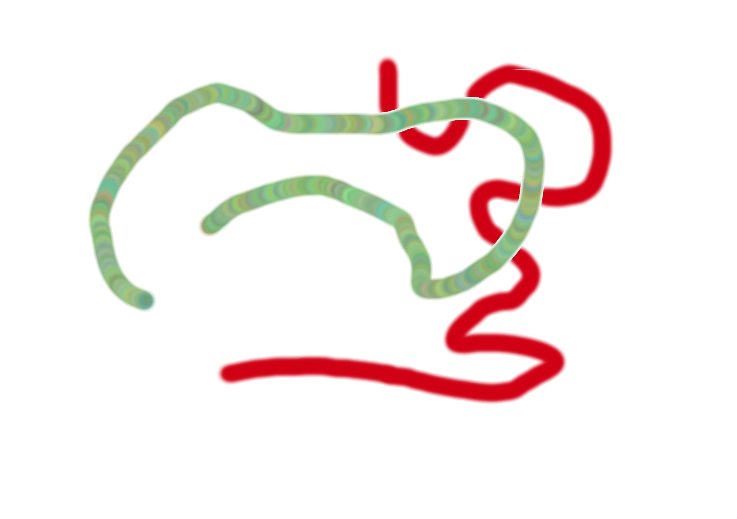
I'm working on a pencil sketch, adding colour. It should be easy, but Affinity Photo v2.6.0 suddenly decided to pull the rug from under me. I wanted to paint with red. I selected a red shade from the colour picker, using RGB values. When I painted, it came out as a mottled blue-green, with brush-width circles showing along the path. If I chose the colour-replacement brush tool instead, it came out as solid red, which is what I wanted, but there were weird artefacts that I didn't want. I've never used the colour-replacement brush before and I don't want to learn how to use it right now to remove those artefacts, I just want to add some red to my drawing! It's almost as though the two brush types have somehow got swapped in Photo. I'm sure the last time I used the Paint brush, it worked OK. I got the same result regardless of what colour space I use on the document. The example is a new document I created in CMYK just to test out the problem. I get the same thing in RGB, and with different colour profiles. I'd assume that a bug has crept in. I've recently moved over to a Win11 PC from Win10, so this may be a contributing factor. In the example the blotchy blue/green line is done in Paint Brush, while the solid red line is done in colour-replacement brush. This is the sort of curve-ball that Affinity tends to throw at me every now and then. I want to get on with my work, and instead end up spending hours doing tests and searching on the web. . . While I was looking into the problem and writing this post, I took up the offer to update to 2.6.2. This fixed the problem. If anyone else has this problem, I suggest doing the update.

-
I've been using the warp group tool on a piece of work in Affinity Designer 2.53. The first time I used it, it worked really well, but when I tried to reproduce the steps on another file (similar art) it wouldn't behave. (That's a different topic!) During the testing of this feature to work out what's going wrong, I've been doing repeated Undo steps to get back to the start point - maybe 20 or 30 steps each time. At some point, one Undo causes Designer to crash and chuck me out to the Desktop. This has happened about three times today. Each time I restart Designer and opt to use the offered recovery file. I can't tell if it's the same Undo step that does it each time (maybe the creation of the warp group itself) or the number of repeated Undo steps that it doesn't like. The warp group is working on a large collection of elements, so it's probably stressing the system. However it worked perfectly well with no crashes on a similar file (same number of elements) a month ago. It's possible that I was still on 2.50 then though. I've noticed that the Affinity software (all three components) seems to be running much slower lately. Whether this is because the Affinity updates have slowed it down or a recent Windows update has slowed the system generally, I can't tell. Win10 Home, version 22H2, build 19045.4651 Dell Inspiron laptop with Intel(R) Core(TM) i3-7100U CPU @ 2.40GHz 2.40 GHz, 16GB RAM, 1TB SSD. Other software running: Edge, Snipping Tool (for screenshots).
-
Dan C reacted to a post in a topic:
Creating a shattered glass effect in Affinity Designer - can't seem to get Divide tools to work.
-
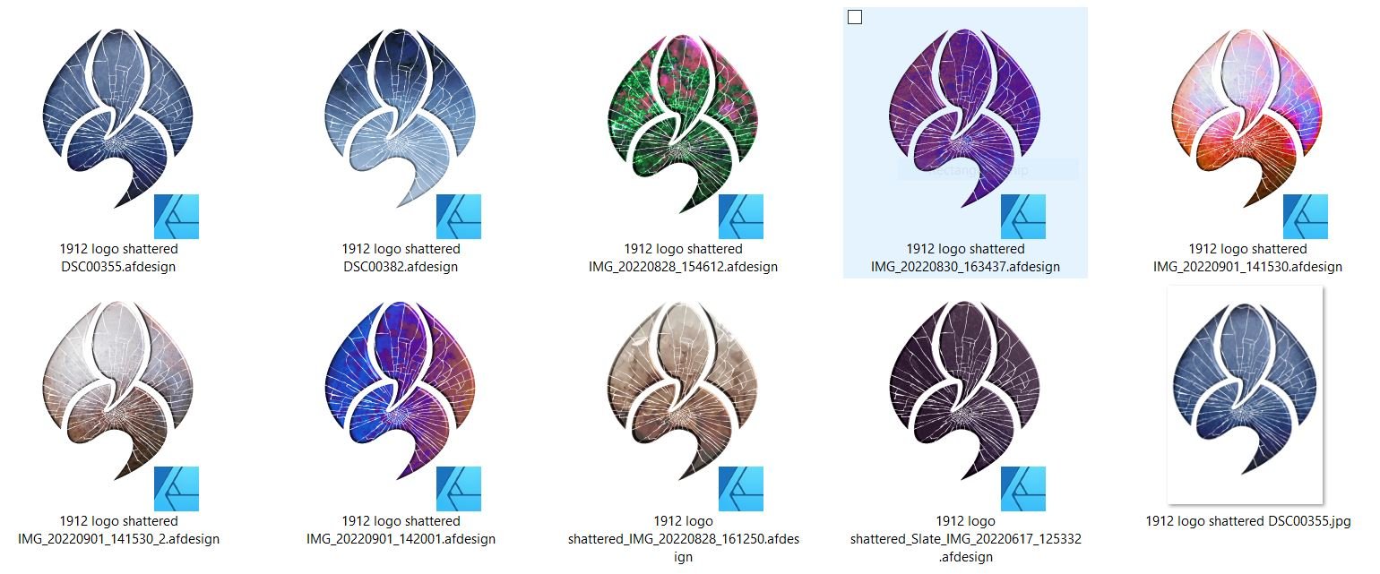
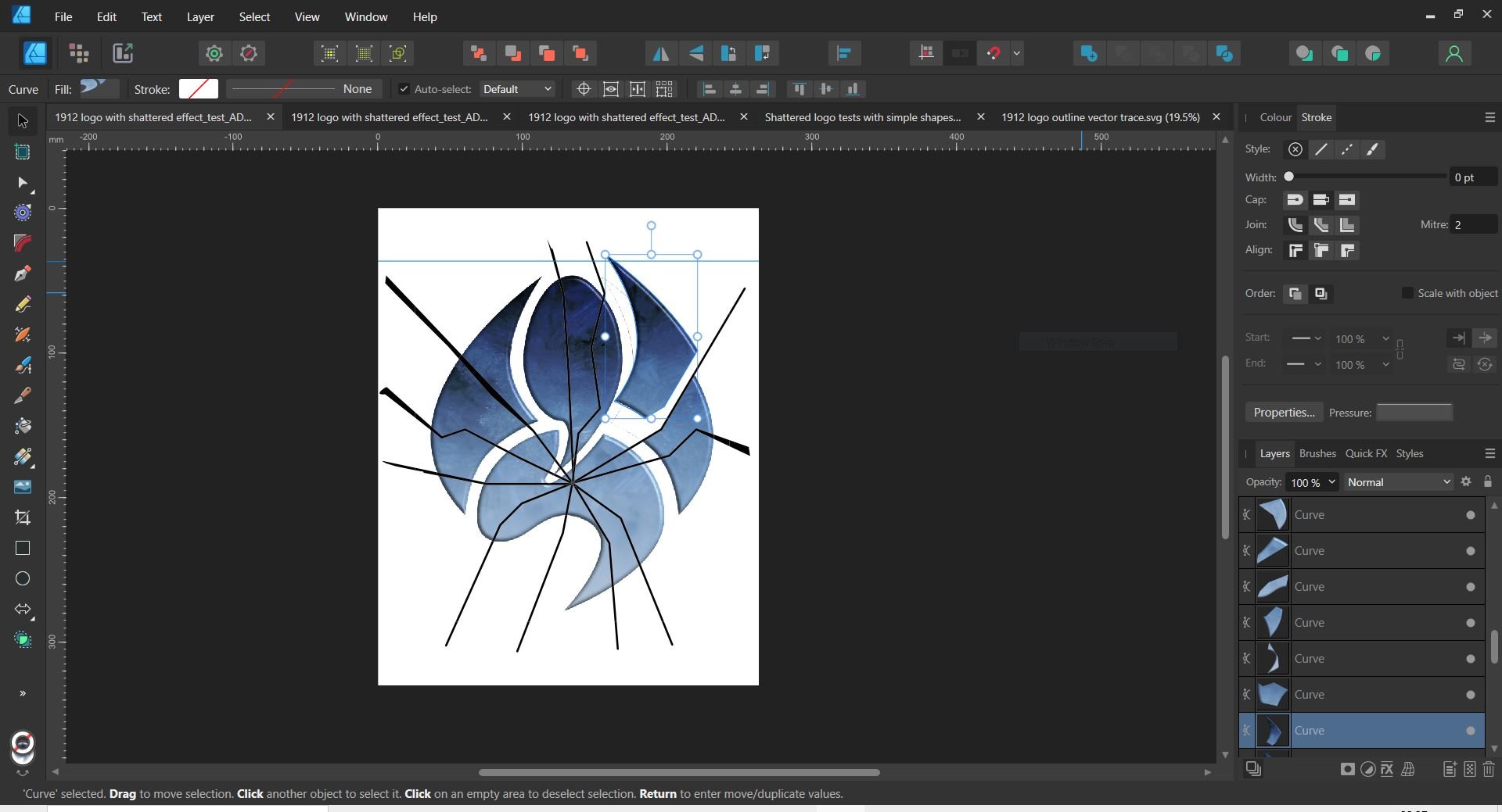
I think it's all done now! Thank you to everyone for all the help, methods and workarounds. I wouldn't have been able to complete the project without it! (Well. the project is not finished yet, but at least I have done the shattered logo part.) I now have a shattered logo in several stages of destruction. I'm not sure which we're going to use as the front cover yet, but I had this nice idea for using all of them on an inner page of the booklet (this is just a portion of it).
-
I don't understand the difference, nor why it sometimes works, and sometimes doesn't. All the images I'm using are similar in origin and construction. How do I turn a bitmap image into an image layer? What I'm doing now is this: *Create my images in Affinity Photo. *Make sure the background is transparent and export each one to TIFF. *Place the TIFFs in the Designer workspace, underneath the layers with the "cracks" and boundary lines that surround the logo's individual shapes. (I stacked several images up, so I could work on them, one by one, in the same workspace file). *Convert one image layer to Curves. (This works for TIFFs.) *Select the cracks (layers grouped), boundary shapes (layers grouped) and the converted image layer. *Choose the Divide tool. *Select and copy the newly-created curves into a new file. *Undo the Divide operation, then delete that image layer, so the workspace is ready to apply the same method to the next image layer. (The delete step may not be necessary - just being careful.) (Note that if I try to do the divide on a layer which is a placed afphoto file, I can't convert it to curves. It has to be exported to a TIFF first - although maybe other older file formats will work too. If I get time, I'll look into that. . .) With the first image I tried, this worked a treat, apart from also creating lots of additional invisible objects, which I'd guess are the interactions of the "cracks" layers and the boundary layers. I can live with having to delete these manually. I thought maybe I could stop these from being created by grouping the cracks group and the boundary group, but no luck. I would imagine that it requires some other logical interaction of the cracks and boundary layers to produce a composite layer before using that layer to divide the logo layers. If I get time, I'll look into that. . . However, with a second image (created in the same way as the first, in the same Photo workspace, just with a different texture layer) it appeared to work OK at first, but it also created new objects for all the cracks too, and these showed as black objects. So the upshot of all this is that on the 1st image I end up with the pieces of the logo with gaps between them (what I want), but on the 2nd image I end up with pieces of the logo with black crack lines between them. I can't figure out why it treats one image one way, and the other image another way. It's barmy! The two texture images were taken on the same camera - possibly even on the same day! So they're quite similar. Oh, and then when I tried to repeat the test on the 1st image, that ALSO now showed up with the black cracks, whereas it didn't the first time. Bizarre! Then I found out that what was happening was that the cracks were still selected, even though their group layer was NOT shown as selected in the layers selector. The workaround is to deselect everything and manually reselect the divided curves layers. Bug! Also of interest: if after doing a divide on an image layer I delete the newly-created curves before repeating the divide process on the next image layer, I get a different result. It also creates curves for the cracks within the same block of new curves. To stop this happening, I have to undo the previous divide operation. I also delete the previous image layer, just to be safe. I can't see why this makes a difference, but it does. I did notice that in SOME (but not all) of the divide operations it seemed to create more objects. This should not happen; every time I run the process it should create the same number of objects. But I think that some of these additional objects are actually the dividing objects, moved down to join the new curves. Again, this looks like a bug, otherwise it would happen every time or not at all.
-
I thought I should be able to do it this way: *Rasterize the shape - this will freeze the FX. *Convert to curves *Use the Divide tool with the cracks as the dividing lines (as before). No luck! Can't convert to curves - it's greyed-out. I've since read that Convert to Curves is only usable on shape objects, and is there to allow the nodes to be edited to make different shapes. Yet it was suggested that I use convert to curves on a bitmap image earlier in this thread and, yes, that worked! Otherwise I would never have been able to get as far as I did using the previous method. I can't get my head around Affinity products. They seem to be very inconsistent in the way they work (or don't work). Maybe they're just buggy.
-
I went right back to the beginning again and tried to do the whole process in Designer only, instead of importing the textured logo render from Photo. That meant using a vector outline version of the logo shapes (I found the file in the end!) as a mask over a texture bitmap. Then I could play with the 3D FX to make it look solid (as I did in Photo), and finally import the shatters layer that I created and refined in the previous tests. It all worked great apart from one problem: as happened right back at the start of this exercise, the shapes created by the divide tool also have the 3D bevel effect - on the edge of every crack. I must have gone through this whole learning curve already, and I'd just forgotten about it. So I'll need to revert to the previous method (as in previous comments) of using complete textured and rendered logos created in Photo, plus an extra layer UNLESS there is a way to "freeze" the FX on a layer without rasterizing it, prior to dividing the shapes.
-
JCP reacted to a post in a topic:
Creating a shattered glass effect in Affinity Designer - can't seem to get Divide tools to work.
-
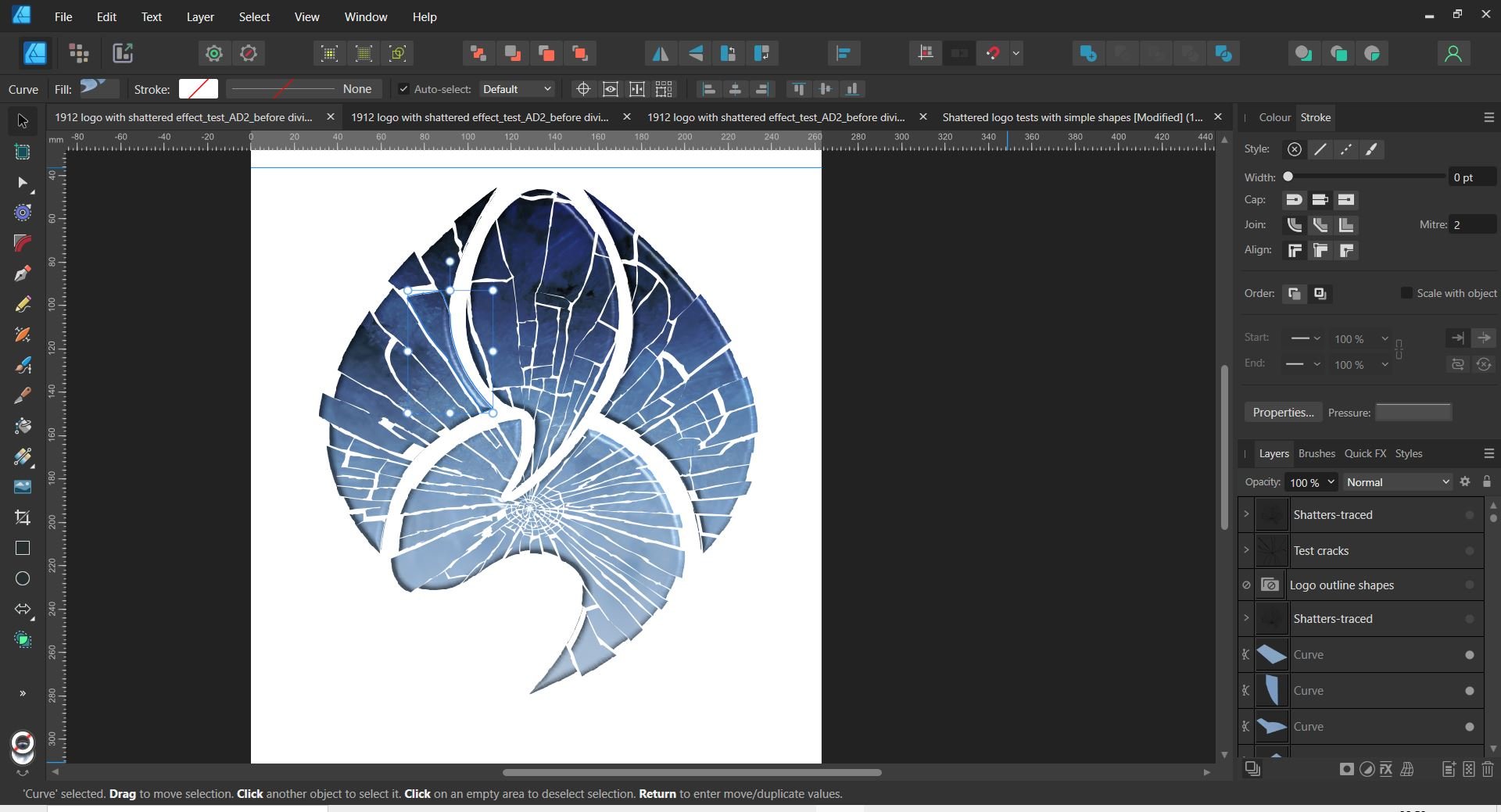
I'm getting really close now! Here's the image with the "real" traced cracks. I need to tweak the shape boundaries to remove that slight residue, but that should be do-able. If only there was some vector shape equivalent of the tools that allow selections to be grown or shrunk in Photo. . .
-
I found that I also needed to set a boundary line around each section of the logo and add these lines to the "cracks" as additional boundaries to divide with so that the broken parts of the shapes would become separate entities. As the logo shape is a bitmap, that meant having to use a 3rd party tool to auto-trace that to vector. (Again! This is where I started all this!) I DO have a vector outline of it because that's where I started the logo design (in AutoCAD, I think), but I'm sure I'd distorted the shape since it was vector, so I wanted to make sure the shape I used matched the bitmap logo shape. Anyway, I got that done using a free online tool, and - success! This test used a simplified, proof-of-concept, set of "cracks". Next step: return to the traced "real" cracks" and repeat the process. This all seems familiar! I'm sure this is where I'd got to two weeks ago. . . At least this time I know more about how the divide tool works.
-
Eureka! I think I've figured out what I was doing wrong. The lines that do the dividing were not always completely spanning the bounding box of the object to be divided. Moving the lines around or changing their shape can affect this. I'll do some more tests. . .