Otto Manuel
-
Posts
240 -
Joined
Everything posted by Otto Manuel
-
 I'm beginning to wonder if the observed result is an actual bug or if Affinity intended for the names to disappear after you Convert to Curve. Does anyone have any idea about the intended result?
 -
Yesterday, while having several objects selected, I stumbled upon the hotkey combo Ctrl + Shift + R, which opens a Rename Layer dialog. Previously, I always renamed my objects or layers by double-clicking on the row in the Layers window and typing a name into the row. For a moment, I thought I might have found a way to rename multiple items at once, so I typed a name in the dialog window and hit OK. The command renamed one of the selected items and ignored the rest. Close, but no.
-
Thank you for observing and confirming that the discarding of names is not OS specific.
-
That thread mentions renaming but seems focused on sorting layers by name. My focus is on simply bulk naming or renaming the objects. For example, I may get caught up in enthusiastically drawing numerous white blobby shapes on a blue background. When I am satisfied with the layout and appearance of the drawing, I may want to change the label on all the white blobs from "Curve" to "Clouds". It would be an effective time saver if I could select all the blobs and name them clouds with a single dialog text entry. For example, I may get caught up in enthusiastically drag-and-drop copies of a leaf shape across my document and arranging them to assemble a drawing of a bush. I may want to select a subset of the "Leaf" shapes and name or rename them "Leaf-dark" or "Leaf-light". Then, I can select that whole subset by name and slightly adjust the color, which contributes color and light value variety to the illustration of the bush. I have workarounds for all of this, some more or less tedious than others. The less tedious workarounds require anticipation, for example, draw a blob and name it "Cloud-medium", then copy the cloud numerous times and edit its shape to provide variety while creating a layout. This type of anticipatory workflow undermines the artfulness of hand drawing. The more tedious workarounds occur after the fact. For example, patiently select and name each and every object with a new name. That is just tedious but can afford significant time savings later in the project's life cycle. 🙂 I have no idea how complex providing the feature may be, but it seems a simple matter to appreciate how useful it would seem to illustrators using Designer. Thank you.
-
Hi, There are numerous occasions when it would be a great time saver if I could simultaneously edit the names of multiple objects by selecting all that I want and naming or renaming them with useful descriptive labels. Can you please add a feature where we can name multiple selected elements with the same name at once? Thank you!
-
Windows 10.0.19o45 NVIDIA GeFroce RTX 3080 Laptop GPU Designer v2.5.6 note: I don't think the behavior is system-specific. The ability to Convert to Curve at the group level seems to be a feature that was introduced in Designer version 2. When working with a group of objects, where each object has a specific name, and using the Convert to Curve operation, the names of the objects are lost, erased, etc. The names shown in the Layers window are replaced with "Curve". While I do not often need to convert an entire group to curves, this feature seems to be the only way to "bake" a warp mesh operator into a warped group, so I will likely use the new Group Convert to Curve feature more often than I would have imagined. It would be helpful if the names of the objects were not lost. I hope this is just a bug rather than an intended or perhaps overlooked behavior and that it can be fixed or facilitated in a timely manner. Thank you! Convert-to-Curve.afdesign
-
Hi, Thanks for taking an interest in this matter. Where would I post a bug report or feature request? In the Feedback forum? Thank you.
-
Hi, Thank you for making some observations and sharing your insights. Yes, you are correct, It occurs when I select a group parent layer & use Convert to Curves on it. It does not occur when I select a shape like a rectangle etc. I should have been more specific. I suppose I have conflated several circumstances where the names are removed, such as expand stroke, and my thinking has been muddled by frustration. It would be nice if selecting a group parent layer & using Convert to Curves on it would not erase the objects' names. Thank you.
-
Designer v2 warp question
Otto Manuel replied to Otto Manuel's topic in Desktop Questions (macOS and Windows)
Now that I have had a brief time to become familiar with this workaround suggestion to turn the elements into symbols, I realize that the names of my elements are not preserved; it just appears that they are preserved because every element is automatically placed within a newly added layer. The name of the element is transferred as the name of the Layer, while the name of the actual element is deleted and substituted with "Curve". This means that in my layer display, I now have twice as many rows to sift through. The names of my elements are still deleted and replaced with "Curve", a bunch of Layer rows are added, and I have a bunch of symbols gathering in the symbol window. Ideally, I could simply *bake* the warp into the group without deleting all the names of my elements. In other words, it would seem ideal if a simple process could simplify the document rather than add layers, pardon the pun, of complexity. Thank you. -
It's a wild guess because I do not use Publisher, but your web-sourced sRGB files might be conformed and displayed in a CMYK colorspace in Publisher, so you can anticipate what the images will look like when they are published in print form.
-
Hi, Thank you for confirming the circumstance. Thank you.
-
Designer v2 warp question
Otto Manuel replied to Otto Manuel's topic in Desktop Questions (macOS and Windows)
So, a genuine troll? 🙂 -
Designer v2 warp question
Otto Manuel replied to Otto Manuel's topic in Desktop Questions (macOS and Windows)
Yes, I do not want to end up with hundreds or thousands of symbols in my symbols panel. Your workaround seems like a good process for retaining the names. If I could find a quick way to delete all the symbols, I would like to. Thank you. -
Designer v2 warp question
Otto Manuel replied to Otto Manuel's topic in Desktop Questions (macOS and Windows)
OK. Perhaps I overlooked the details of this suggestion. Are you suggesting that I temporarily make every element in my warp group a symbol and then convert to curve the group? I tried that and it works. Thank you. Then I detached the group so I could clean up my symbols window... and figured out that I must right-click each unwanted symbol to delete them. A brutal non-time saver. I had hoped that Warp would be a nice time-saving feature for my use case, but it is beginning to look like hand drawing various iterations is going to be quicker than using warp. Thank you. -
Designer v2 warp question
Otto Manuel replied to Otto Manuel's topic in Desktop Questions (macOS and Windows)
I can't tell if you are being genuine or trolling, but suggesting that I make my groups' numerous elements into symbols seems ridiculous. I try to make good use of symbols when they make sense and are efficient. My illustrations would end up with hundreds or thousands of symbols. It would be a nightmare of procedural processing. That seems like a heavy-handed solution for retaining element names when baking a warp. -
Designer v2 warp question
Otto Manuel replied to Otto Manuel's topic in Desktop Questions (macOS and Windows)
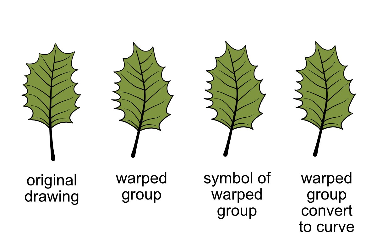
Just in case someone wants to look into this without making their own quick test file here is a Designer v2 project you can inspect: Leaf-Warp-Group.afdesignLeaf-Warp-Group.afdesign
-
Designer v2 warp question
Otto Manuel replied to Otto Manuel's topic in Desktop Questions (macOS and Windows)
I just made a symbol out of a warped group, and it became a symbol. It became a symbol with a copy of the same warp operator superimposed upon it. The group's constituents still have all their names, but the warp is not baked into the shapes. It's just like a copy-paste of the group with the warp operator sitting on top of it, but it is a symbol. I want to keep the warped shapes and lose the warp operator. Thank you. -
Designer v2: Can I name multiple elements with the same name at once? For example, suppose I Shift > Select a bunch of bird figures labeled "Curve" in the Layers display and then name them all "Birds" with one text input. Then all my birds would be labeled "Birds", and I could stay organized more efficiently. That would be a time saver. Is it possible?
-
Designer v2: Does Convert to Curves have to erase the names of the elements converted? Whenever I make a drawing, I habitually name every element, regardless of whether it is an object or a curve. Whenever Sometimes when, I use Convert to Curves, the names disappear. I would like for that not to happen. Is there an option to preserve the names? I like to use Select > Select Same > Name to select and make minor adjustments to the color or stroke of multiple objects simultaneously. It always seems like a waste if time to have to rename all the elements that have their name lost.
-
Designer v2 warp question
Otto Manuel replied to Otto Manuel's topic in Desktop Questions (macOS and Windows)
I currently cannot directly generate Affinity Designer files or create documents in its proprietary formats. However, I can guide you on how to create a "warp group" in Affinity Designer and explain the steps to set it up with your objects just before the "convert to curves" operation. Steps to Create a Warp Group in Affinity Designer Create Your Objects: Place the elements you want to include in the warp group (text, shapes, images, etc.) on your canvas. Group the Objects: Select all the objects you want to warp, then group them using Ctrl + G (Windows) or Cmd + G (Mac). Apply Warp: With the group selected, navigate to the Warp Tool (this is often part of the toolbar or under the Layer Effects menu, depending on your Affinity Designer version). Choose the warp type you want to apply (e.g., perspective, arc, or custom mesh). Adjust the warp handles to achieve your desired distortion. Before Converting to Curves: At this point, your warp group should be editable, allowing you to tweak the objects or warp settings further. Save the document in .afdesign format to retain the warp settings. If you need a detailed workflow or help setting up specific objects, let me know! OpenAI. (2024). ChatGPT [Large language model]. https://chatgpt.com -
Designer v2 warp question
Otto Manuel replied to Otto Manuel's topic in Desktop Questions (macOS and Windows)
I should add that all the components in my group "Leaf" were already curves. I am familiar with the fact that in v1 Convert to Curves deletes the names of each component. I only used Convert to Curve to commit the warp. I am hoping there is a better way to do this. Thank you. -
Hi, I am a new v2 Designer user looking forward to using the warp feature to make iterations of group assets. For example, I have a tree leaf, compiled as a group, that I illustrated by hand, and now I want to make variations of the group using the mesh warp. I will use the variations in an assembly to depict a tree with 100s of leaves, so I prefer to destructively commit to the warping. I used the mesh warp to distort the reference shape into a new shape. Then I used convert to curves to commit the warping. I immediately noticed that the name of each component in the leaf had been deleted. Names such as LEAF SHAPE, LEAF OUTLINE, VEIN, and STEM disappeared. I use these names to make selections. When I make my hand drawings, virtually every component I draw is assigned a name. It is counterproductive to me for the names to disappear. Is there a better way to commit the warp? Can I commit to the warp and retain the names of my grouped assets' components?
-
Thank you. I am going to upgrade with this offer.
-
I imagine it would be possible for Affinity to grant upgrade discounts to individual application licenses even though Affinity says it can't imagine how it might be possible. 🙂
-
I apologize, I should have elaborated on the details of the circumstance I was describing. At the City Market, I spoke of the Special Offer label (usually yellow and red to attract attention) that reads something like "Buy 2 for $2.00." These labels are placed underneath the "regular" price label (usually black and white throughout the store), which might read $3.49. If you notice the finer print on the label, you can see an appendix to the offer explaining that you can also pay $1.00 for a single item. The pricing always seems to be up to date in the SKU database, automatically honored at the checkout kiosk, and documented on the printed receipt. Speaking for our family, we greatly enjoy purchasing items we regularly use at reduced prices and purchase quantities that seem sensible for our usage patterns. So, all the customers benefit from the "Special Offer" offer. Obviously, the proprietors are suggesting that people select two of the items, but they also seem to realize that any extra sales of individual items made at the lowered price are not harmful. The incentive: Customers can save more money by buying more items if they actually use the extra items they collect. I never thought about it, but perhaps this annoys customers who do not feel as "special" when they realize the reward for purchasing more is not exclusive to those who choose to do so. City Market's marketing department seems to believe that its customers, on average, enjoy the special offers in the manner it has made customary. Thank you.