Otto Manuel
-
Posts
240 -
Joined
Everything posted by Otto Manuel
-
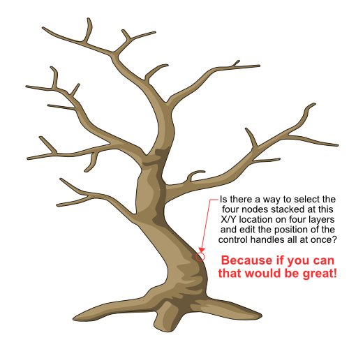
 I have a habit of drawing a crude shape, such as this tree trunk, and then copying the bottom layer to make shading effects layers, as well as an outline layer. The extra layers stack on top of the basic shape. The example shown here has four layers stacked upon each other. After I do this, I frequently want to edit a node's control handles. Often, making such edits causes me to have to edit the control handles on nodes in the other layers so everything remains aligned. Depending on the need for precision, the exercise of aligning the nodes and curves can be easy or painful. Am I missing an opportunity to do this more easily? What's the best way to accomplish what I am trying to do? An example project has been uploaded in case it is helpful for demonstration etc. Thank you! Multiple-Nodes-Edit-01.afdesign
-
2.6.2 Designer: buggy offset
Otto Manuel replied to Tormy's topic in Desktop Questions (macOS and Windows)
I made a quick test with offsets after reading this thread on Sunday. I found it was easy to reproduce the problem with the display. I could not reproduce the issue with an export. In other words, when the display was buggared the export still looked good. -
As a reminder, this thread's original focus was on Affinity Designer 2 and its buggy Warp Group issues when the Convert to Curves command is run, rather than a not-so-smart debate about smart nodes, which may or may not be smart enough to warrant debate. If we are going to digress into an off topic debate can we please discuss the advantages and disadvantages of using the Convert to Curves command on a warp group to one-click instantly erase all the layer names in your group? Subtopics could include subject lines like "how many is too many?" For example, is losing the names of 99 layers and then patiently renaming them one by one acceptable to you? Would 100 layers be too much? What is the threshold before losing names to an oversight/bug/fubar becomes frustrating and or intolerable? 🙂 Good times!
-
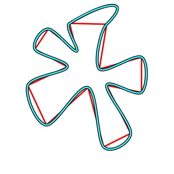
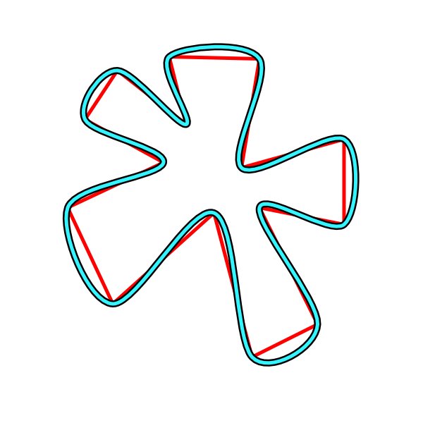
Like this?: IOW, I don't see any difference at all. As mentioned, I most often observe a slight difference when grabbing a Smart Node and moving it. With the uploaded test project, it is easy to test for changes to the curves. The conveniently labeled layer names make it easy to keep track of the changes that you make. made.
-
I was joking about the Affinity Designer 2 Smart Nodes; they don't seem much smarter than Smooth Nodes. I have set up specific tests to compare the two types of nodes and how they respond to editing. It takes a lot of effort to make a difference in how the two react. When there is some slight difference, neither result is necessarily preferable. I have attached an example of a test project, with three descriptively named layers, indicating the use of Sharp, Smooth, and Smart nodes. If you grab one of the Smart Nodes and drag it, you may notice the neighboring nodes rotate slightly, or you might not. If you grab the corresponding node from the smooth node layer and drag it to the same place where the smart node was dragged, you should notice that the adjacent nodes do not rotate. After dragging the nodes, even when I notice the difference in the resulting curves, I find it hard to answer the question: Does it matter? Maybe? Maybe not? Nodes-Test-01.afdesign
-
But, But, But... I like Smart Nodes. 🙂 Thanks for taking a look and figuring out a solution. I converted my Smart Nodes to Smooth Nodes, and then I was able to one-click erase-all the names of all my layers without distorting the shapes. Thank you.
-
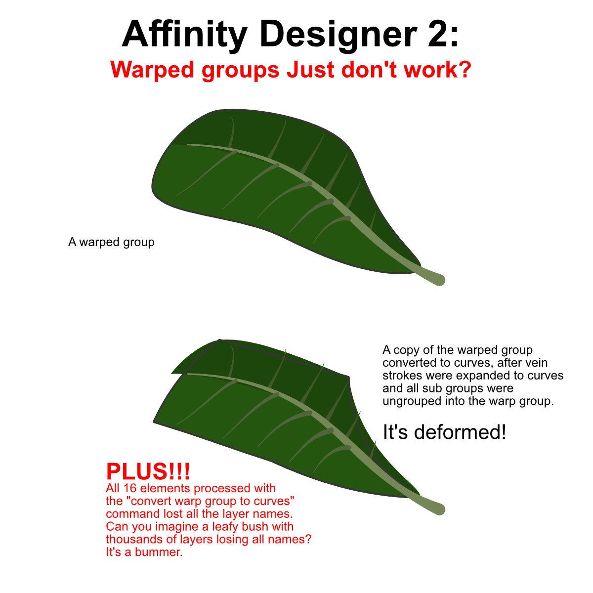
Affinity Designer v2.6.2 OS Name Microsoft Windows 10 Pro Version 10.0.19045 Build 19045 Processor 11th Gen Intel(R) Core(TM) i9-11900H @ 2.50GHz, 2496 Mhz, 8 Core(s), 16 Logical Processor(s) Installed Physical Memory (RAM) 32.0 GB System Manufacturer Micro-Star International Co., Ltd. System Model Creator 17 B11UH Graphics NVIDIA GeForce RTX 3080 Laptop GPU Here is an example project featuring a leaf. I have a big leafy bush with many leaves. The problems manifested with this single leaf are multiplied by the number of leaves in my leafy bush. It's a bummer. Is there a way to use warp groups without wishing you didn't? Feel free to take a look at the attached test project. WARP-TEST-01A.afdesign
-
I would love to be able to search by layer name. Using a search feature would be like using a computer in the 1980s, except it would be 2025. Search would make life easier, save time, and preserve more energy for creativity to flow. Wouldn't that be fun?
-
Select multiple layers and edit multiple layers' names at once. For example, let's say you have a warp group with one hundred ants and a sugar cube in that group. Then you process the warp group with convert to curves. After that you would like to select the one hundred ants and label all of them "ants" with one operation, rather than selecting and naming each layer in a sequence of one hundred operations. Wouldn't that be fun? It would save some time too. Thank you!
-
Yes, The display issue, with the distortions and the temporary cut-off, happens to me too frequently for me to think that it is specific to a particular file. I have imagined it was a graphics processing issue that occurs on a subset of computers, and I continue to hope that someone may have learned of and can suggest a setting that prevents it from happening. I can appreciate that some have never encountered the issue, but I also know some do. Hopefully, someone will recognize the issue and figure out a solution. However, the initiation of this thread was inspired by the seeming permanence of the cut-off. As I mentioned, I was unable to "jog" the display back to normal. I have since learned that the impression of permanent cutting off is caused by masking, which was applied when I used an adjustment layer. When I removed the adjustment layer, my experience became familiar again, which is to say "the distortions and the temporary cut-off happen to me too frequently for me to think that it is specific to a particular file." I can live with that. It does not seem necessary that the distortions have to occur, but I have been working with it for many years. Thank you.
-
My current need is to process Warp Groups with Convert to Curves to work around another bug. The warping effect often extends shapes beyond the perimeter of the bounding box, and Adjustments and masks behave erratically outside the confines of the bounding box of the group. Converting the warp group to curves works around that problem, but introduces the issue of disappearing names. I love working in Affinity Designer, but I find myself spending a lot of time on housekeeping tasks.
-
The workaround is helpful, but it does not solve the problem when you have to select and process at the group level. For example, If you are trying to process a Warp Group with a Convert to Curves command, you are basically doomed to lose all the carefully assigned layer names. With my latest project, I am confronted with the need to process warp groups by converting them to curves, so that the bounding box resets to the span of the warped elements. If I proceed to convert the warp groups, I will lose several hundred carefully applied names, which will then make it nearly impossible for me to use the powerful Select by Name command to make global-level color tweaks to my carefully planned project layout. It is a very frustrating dilemma. Thank you.
-
Convert to Curves wipes all my carefully selected layer names and leaves them labeled "curve". It's got to be a bug; who would want layer names they have patiently typed into the layers panel to disappear? This issue causes me an unfathomable amount of time when I run a Convert to Curves command and then have to rename everything. It's a bigtime bummer. Is it on the fix list? Thank you.
-
I've just figured out that in the composite illustration, I was using a Vibrance Adjustment on the group, which created a mask that I suppose caused the persistent cropping. But this does not explain why the problem even occurs in the first place. Additionally, I am applying adjustments to many of the other groups in the composite illustration, and they exhibit the same problem. I had not noticed it because of the density of the overlaid elements. In the second example, which shows just the single group, there are no adjustment layers involved, which is probably why I can restore the display by adjusting the zoom, position, etc. So, I have two problems: one where distortions and on/off cropping occur, and another where the adjustment masks will not extend beyond the bounding box.
-
When I refer to assets, I mean simply the elements that I have illustrated in other project files, which I use as reference files. I copy and paste my assets into new files. I am not using any of the asset features or the asset panel. And, as I mentioned, the display issue occurs frequently across many projects.
-
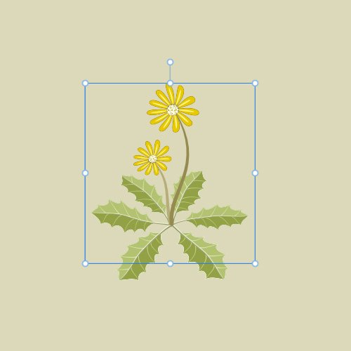
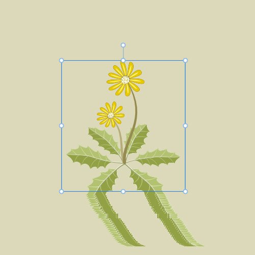
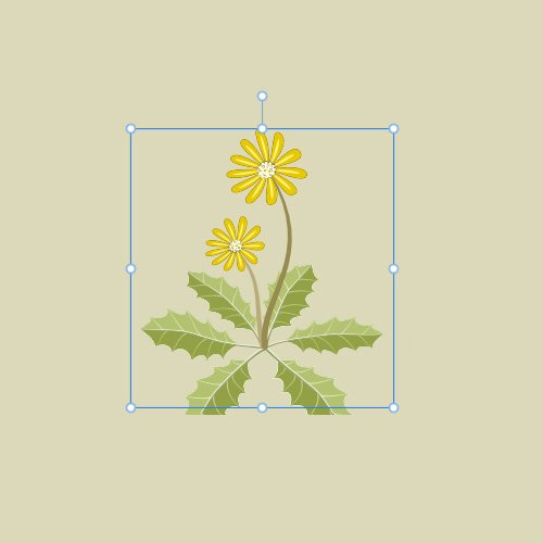
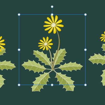
Hi, Thank you for taking an interest. All of the graphic assets I have created exhibit portions that extend beyond the bounding box. As I say, I often do have issues with this. The other assets that I have pasted into my composite illustration are working ok, but in this case, I can not get this particular group to settle the matter. Here is an example of the same asset element pasted into a brand-new file. I copied and pasted the group into a new project file. Everything looks fine. I dragged the group around the artboard, and the distortion I mentioned appears. I dragged the group some more, and the distortions disappeared, but the clean cutoff appears and persists. With just this single group in the project, I can likely get the element to settle down and display properly. However, in the complex composite illustration I intend to use this group in, the problem seems persistent. I am hoping there is a way I can learn to prevent this. Thank you.
-
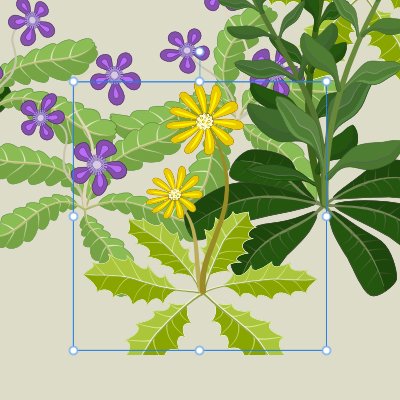
Affinity Designer v2.6.2 OS Name Microsoft Windows 10 Pro Version 10.0.19045 Build 19045 Processor 11th Gen Intel(R) Core(TM) i9-11900H @ 2.50GHz, 2496 Mhz, 8 Core(s), 16 Logical Processor(s) Installed Physical Memory (RAM) 32.0 GB System Manufacturer Micro-Star International Co., Ltd. System Model Creator 17 B11UH Graphics NVIDIA GeForce RTX 3080 Laptop GPU Hi, I have a problem that occurs not infrequently, but it almost always works out okay. Today I am stuck. Occasionally, or perhaps often, when I am editing, moving, or zooming a group of elements, I see cut-offs or distortions on the display of the artboard. I usually reconcile this by purposefully zooming the view in and out to "jog" the display's memory. I imagine that zooming the view somehow refreshes the display, and the entire grouped object will suddenly become displayed as a whole. Yesterday, I created some grouped elements and encountered the issue, but the procedure above resolved it. Later, I started copying and pasting the grouped elements into a composite illustration and found that one of the elements was persistently cut off at the bottom. I can not get it to display properly. Here is a cropped image of the file where I created a collection of several grouped elements, which I consider graphic assets. I captured a screenshot with the blue boundary lines, as I believe it may be a clue to why the issue is occurring. FWIW, the assets include group warped layers. Here is a cropped image where I have copied/pasted some of the graphic assets into another file as I begin to assemble an illustration. Notice how the lower portion of the leaves has disappeared. As I mentioned, I frequently encounter distorted fragments or disappearances like this and can restore the display, but in this case, I am stuck. It occurs to me that it's time to identify the underlying problem and utilize Affinity Designer's features more effectively. Can you please suggest a solution? Thank you!
-
Feature Request: Add a Sine Wave to Shapes Thank you.
-
I can't recall ever seeing them in my old Win 7 Designer 1 install that I had used for many years, but I opened up v1 on my new Win 10 laptop install, and sure enough, they are there. I think they would have bugged me long before having recently noticed them on my new v2 install. I can see why some would like them, but I feel like they are just distracting. Thank you.
-
Hi, I have noticed on a few occasions that the names in the layer column of my TEXT objects include a line break symbol that I would expect to be hidden. Is that a selectable option that I can turn off? Is it a bug? Is it intended behavior? Designer v 2.56 Win 10 x64
-
Thank you for the info.
-
I suppose it is just an obsession on my part, but the thought that I might have two nodes snapped to the exact same X/Y coordinates bugs me. Nevertheless, I often join them to assemble bi-symmetrical shapes. Is there any Affinity documentation that mentions that the Designer recognizes the "stacked" pair of nodes and removes the redundant node from the project? Thank you.
-
Designer 2: Mirror objects on axis and join? Hi, I often mirror a Curve by using Transform Flip copy functions and then slide the new copy to align with the objects' edges. With other apps, you can mirror an object along an edge and know the nodes are perfectly aligned. Some apps even let you eliminate duplicate nodes that share the same coordinates. What is the best way to perform a mirroring of curves, joining of curves, and eliminating redundant nodes? Thank you.
-
If a group consists of multiple items and all of them are curves, you may run the Convert to Curves command. When you do, the group's name and each curves' name is lost. If a group consists of multiple items, such as some curves and at least one procedural shape, you may run the Convert to Curves command. When you do, the group's name and each items' name is lost. If a collection of non-grouped objects is selected and one or more objects are procedural shapes rather than curves, you may run the Convert to Curves command. When you do, the names are retained.
-
Hi, Thank you for the suggestion. I have done that many times. It can be an effective way to waste 15 or 20 minutes. 🙂 Sometimes, when I draw, I realize I am skipping the naming, and if I want to use names, I must return to the task later. On those occasions, It feels more important to follow the sketcher's muse. It is not unusual to end up with hundreds of little curves that have been drawn and are candidates for naming. On other occasions, I "engineer" an illustration with step-by-step intent, and I make time to name elements as I introduce them to the project. I would appreciate the ability to draw freely and then name the elements afterward in the most efficient manner. Thank you.