Search the Community
Showing results for tags 'dimetric'.
Found 4 results
-
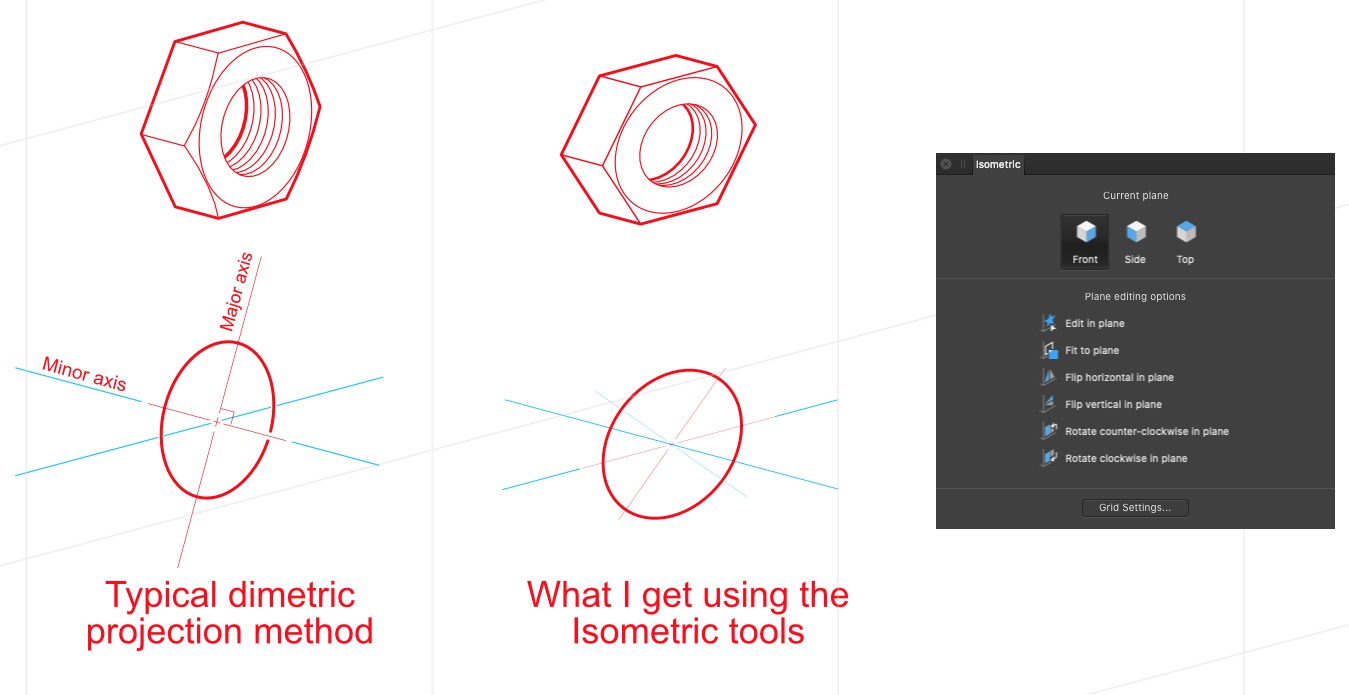
 Sorry if this has been discussed before. As a "traditional" technical illustrator, i.e. I learned on a drawing board, I am confused about how the isometric tools are supposed to work. I understand the basics but am confused with the results. I am using a 15° x 15° dimetric here. Traditional illustration states that with an ON AXIS ellipse the minor axis should be at a 15° angle (parallel with the drawing plane) with the major axis perpendicular to the minor axis. When I use the isometric tool this does not happen. (see the attachment please). There is some skewing or somewhat perspective type of adjustments being made here that is not making sense to me. Perhaps there is someone out there with a similar background as myself that could please explain to me the expectation of this tool? Note: In the attached example the image on the right started as a 2D image, I then used the Fit to plane command to create the final position.
-
 I don't know if there is a reason this isn't possible or if I am missing something, but I can't get the plane set of any grid type but isometric to align with each other. When I make an isometric projection of a cube every plane of the grid just aligns and all the faces of the cube can join like this: But when I make a dimetric projection the planes don't align with each other and the faces of the cube can't align with the grid: I know I can just join the faces together anyway, but then the cube wouldn't align with the whole plane set. I don't know if this is possible, but I think a solution would be to shift the plane consisting of the first and up axis, and the plane consisting of the second and up axis down or up to align with the plane consisting of the first and second axis. I also found this topic about the same problem, but the solution given there is to alter the spacing of the up axis instead of shifting the whole plane. This would also alter the proportions:
-
 I want to work using a dimetric grid with the "Create plane set" option checked however I can't figure out what spacing is required to get the grid lines to intersect on the different plane sets. Screengrab attached to illustrate what I'm talking about. Absolutely love the way the grids/plane sets work for isometric and really hope it's possible to find the formula to get it to behave with non-isometric projections.
-
I work as a technical illustrator (as well as graphic designer, photographer, and technical writer). I have both a PC and a mac, but want to work full time on a mac and get out from under Microsoft and Adobe. As a technical illustrator it is very important to draw at very specific and consistent angles, and be able to create precise ellipses based on drawing angle. Illustrator and CorelDRAW make it very easy to create these ellipse by using actions and macros. There is also the ability to set smart guide to draw at specific angles. I fail to find any tools like these in AD, specifically 1) create or control constraint angles 2) smart guide 3) scale an object (like a circle to make an ellipse) by percentage, in one direction only, and 4) rotate that ellipse at a specific angle. I have been known to miss the obvious, so please tell me these if I have missed these in AD, or if they will be added sometime in the near future. BTW, Serif DRAW has a FANTASTIC tool for drawing "on-axis", great for the tech illustrator. This would be perfect for AD. One last thing, I created an image and thought I would change the colors or this object and used a layer filter (not sure what it is actually called). Sadly, when exporting to either EPS or SVG, it is converted to a bitmap. In fact, many effects such as gradient fills are converted to bitmaps when exporting to a vector-based format, which is really a show stopper for me. A way to actually created a global swatch library that can they be changed would be great too. thanks