Search the Community
Showing results for tags 'Distort'.
-
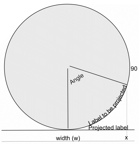
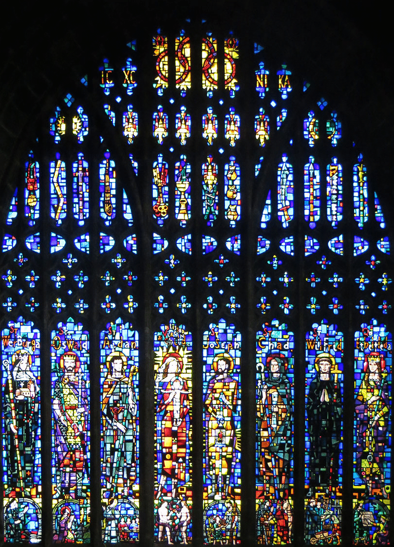
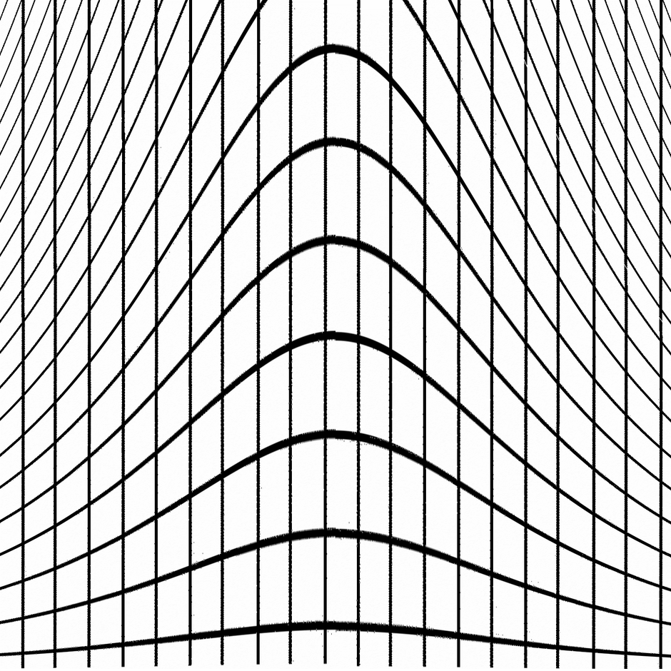
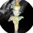 In a recent post in Questions, @Maxxxworld asked how he could warp an image to apparently wrap it around a bottle. I posted a solution to his problem there, which I expand upon here. Consider the facing semicircle of the bottle as seen in this diagram: The visible part of the label extends from -90 degrees (on the left, not shown) to 90 degrees on the right. This will correspond to the width of the original image. This will project onto the final width of the image (the line below). The final width is less than the original width by a factor of pi/2. A bit of trigonometry shows that the sine of the Angle indicated is given by (x-halfwidth)/halfwidth, where halfwidth is both the label and the final image. Putting this together and re-arranging a bit gives us an Equation: x=(asin(2*x/w-1)*w/180)*pi/2+w/2 A bottle is typically viewed from above, so that the label has a curve, typically with a dip in the middle.This can easily be simulated using equations, using: y=y-Const*x*(w-x)/w/w The Constant determines the depth and direction of the curve. I have used the expression w*(0.5-a) as a scaling factor, where a is a parameter chosen at runtime. This will change the curve from negative (curving down) at the default a=1 to positive at a=0. Inserting this into the equation gives: y=y+(0.5-a)*x*(w-x)/w Note that the w in the numerator and denominator cancel out. The value of (0.5-a) determines the curvature as described above. As an example, here is the Great West Window of Chester Cathedral. I chose this because it has lots of verticals to see how the filter affects it. (It has verticals once I had put it through the Mesh Warp.) And here is the image after the filter: Before filtering I cropped it close to the sides of the window and then Rasterized it to remove the invisible sides. I then added space at the top and bottom to allow room for the curvature part to operate. I then followed this by Clip Canvas to remove surplus transparent ends. The calculations for this filter are complicated by the algorithm that Affinity uses to effect these equations, which I explain in this Tutorial here. I have created a macro that effects the filter, and then uses Clip Canvas. By clicking on the cogwheel, you can alter the degree and direction of curvature. EDIT: I have discovered that this macro will only perform once (per Affinity Photo session). I add here a version recorded in version 1.8 which does work properly in Photo 1.8: WrapAround1.8.afmacro I alos onclude here the original macro, recorded in version 1.7: WrapAround.afmacro John
- 20 replies
-
- 14
-

-

-
 Hello, How to distort text like in Adobe Illustrator like a flag or arch ? How to distort horizontly or verticaly ? Thanks for advices.
- 5 replies
-
- 1
-
-
- artistic text
- designer
- (and 2 more)
-
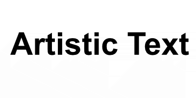
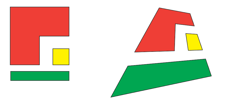
I recently had difficulty in getting the Distort > Equations Filter to work as I thought it should, I was convinced that there was an error and posted a Bug report here. After comment from members @shojtsy and @walt.farrell and moderators @Andy Somerfieldand @Patrick Connor, I finally got it sorted. I thought that an item in the Tutorials might help for others coming to this problem anew. Consider a simple pair of Equations: x=x+y*0.2 y=y*0.7 My original thoughts were that these represented algebraic transformations, that the value of the pixel at position (x,y) would be moved to pixel position (x+y*0.2, y*0.7). Applying this to the image: gives: The bottom right corner of the image is transparent. My expectation was that the height of the text would be reduced to 70%, but it is actually expanded to approximately 140% (1/0.7). I originally expected the slant to be anti-clockwise, but it was clockwise. My original thoughts and expectations were wrong. What actually happens is quite different. For any pixel at position (x,y), Affinity Photo will find the pixel at (x+y*0.2, y*0.7) and use the value of the pixel value there to apply to the pixel at (x,y). Following this logic, the results are consistent with (revised) expectations. John
-
 Hi guys, Is there a DISTORT TOOL or something similar to the distort tool from Fireworks, which allows to distort images? Thanks
 -
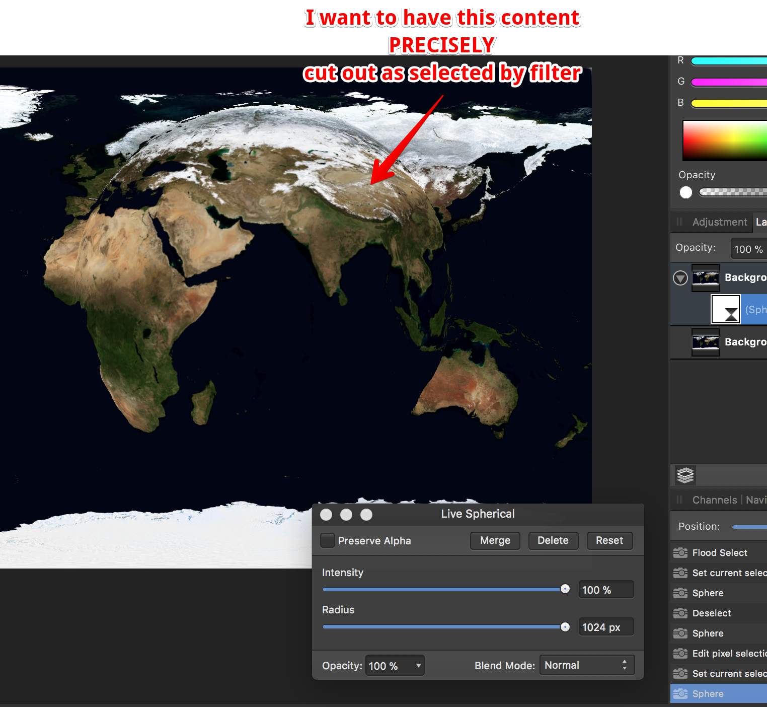
 How do I cut out precisely (!!!) the range I selected with the distortion filter "Sphere" - no matter live or destructive. I tried everything, giving up... FYC: if I make a circle selection first, I never get the range spherized I want to... Why is this filter limited to 1024 pixels??? Thanks for all reply in advance
-
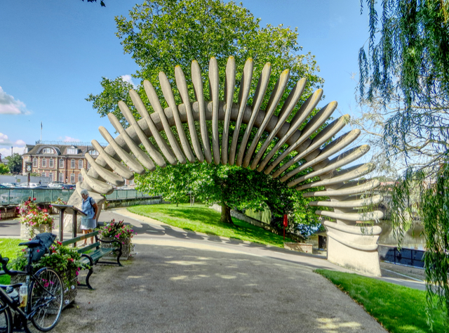
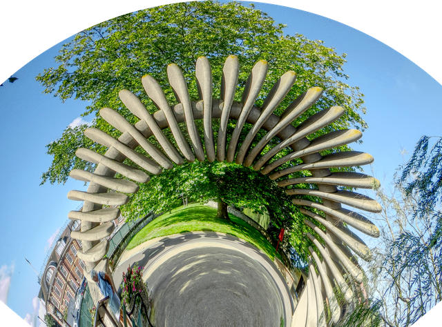
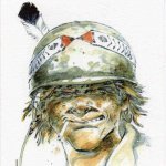
Conversion of a rectangular image to polar co-ordinates using Equations is not straightforward. A major problem is that the origin of the rectangular Cartesian co-ordinates is the top left, whereas for a polar display, you would typically want the origin on the midline, probably near the bottom. The following equations assume that the origin is in the midline along the x-axis, and at or near the bottom on the y-axis. First select Filter > Distort > Equations and enter: x=w*atan((x-w/2)/(h/a-y))/100+w/2 y=h-sqrt((x-w/2)^2+(h-y)^2) The expression (x-w/2) displaces the horizontal origin to the centre, and the expression (h-y) displaces the vertical origin to the bottom. In the first formula, for x, there is a parameter a, which allows you to scale the polar transformation; reducing the parameter a stretches the image around the circle. The 100 is an arbitrary scaling parameter which seems to work. The expression +w/2 at the end re-centres the image. This seems to be necessary, but I am not sure why. I would have expected to deduct w/2 rather than add it! Here is an original image of the Quantum Leap statue in Shrewsbury: With this transform using the default parameter a, this produces a quadrant. And with the parameter set to approximately 0.6: Here is the Macro: PolarQuadrant.afmacro The first thing the macro does is to unlock the image. I tend to do this automatically in macros. It is probably unnecessary. I ought to be able to give the adjustable parameter a, a name, but I have not been able to do this. John
-
 Hi, I'm new here. I bought Designer an hour ago. Do not anyone know where to find distort? Thanks Mak
-
@atfitzy posted a thread about re-shaping a text block. I tried various Equations in Filter> Distort and the best I could come up with is: x=x y+(h-y)*(w-x)*x/w/w/a This produces the required arch in the upper margin of the block. The a parameter allows the user to increase the stretching effect. The default of one has no effect; reducing it will increase the effect. However, I find that reducing the parameter has no effect until the value goes below half, after which it has the desired effect. I can get the desired effect by putting a multiplier at the start of the equation: y+2*(h-y)*(w-x)*x/w/w/a Here are a couple of arched images using this formula: Otherwise the formula works as desired. Before I commit this to a macro can anyone explain this unexpected behaviour in the parameter value? John
-
I have been using Filter > Distort > Equations to modify text onto a sine curve. First I rasterize the text, then apply Filter > Distort > Equations with the following formulae: x=x y= y+(h*a/2)*(b*sin(360*x/w/c)+(1-b)*cos(360*x/w/c)) This filter works as intended as a one-off, and whilst recording the macro, but If I then export the macro, and try to apply the macro later nothing happens. The history panel shows that it has been applied, but the image is unchanged. This happens whether I load the macro as a single macro, or if I add it to a library and load it from there. Text onto sine-cosine curve.afmacro Anyone any ideas? John
-
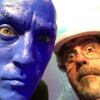
The equations facility in Affinity is not well documented. There is limited support in some AP actions, but the Transform and Distort > Equations filter offers a wide range of functions. This tutorial focuses on using the trigonometrical functions, sine, tangent and arctangent. The argument to many trigonometrical functions is an angle. In mathematics this is usually expressed in radians. However, the Affinity functions expect their argument in degrees. Sines and cosines The argument expected is in degrees, and over 360 degrees, the value of the function varies between -1 and +1. The sine function starts at zero and rises to a maximum at 90 deg, then falls to zero at 180 deg, falling to a minimum of -1 at 270 deg before rising to zero at 360 deg. If we wish to map this cycle to the width of an image, then we can use sin(360*x/w). Typically we would want the amplitude of the cycle (the maximum and minimum) to be more than 1 and -1, so we add a scale factor, measured in pixels. For an amplitude of 100 pixels, we have 100*sin(360*x/w). This gives one cycle across the width of the image. If we want more than one cycle, we can add a multiplier in the argument, so for three cycles per width, we can use 100*sin(3*360*x/w). Note that I use 3*360 rather than 1080 since it preserves the standard 360 multiplier. As an example, here is a checkerboard with Filter > Distort > Equations: x=x y=y+100*sin(2*360*x/w) If we apply this to a real image, we get: This is varying the vertical position of a point along the x-axis. We could vary the vertical position of a point along the y-axis by using the equation: y=y+100*sin(2*360*y/h) For the checkerboard, this would give: And for the Severn Bridge we get: We could even combine them both with the formula: y=y+100*sin(2*360*x/w)*sin(2*360*y/h) to give: or, for a real image: I will be adding further examples using tangents and cotangents.
- 9 replies
-
- 4
-
-
- trig functions
- equations
- (and 1 more)
-

Distort / warp feature affinity designer
Guest posted a topic in Feedback for Affinity Designer V1 on Desktop
Dear serif. I am a logo designer. I bought affinity designer for logo designing. Every logo designer needs mockup But affinity designer doesn't have warp effect so you can't have mockups. The only way to use mockups is by buying affinity photo (50$). Dear serif. Be sure that i won't pay another $50 And if i didn't get the warp tool in the next update be sure that i will leave this program -
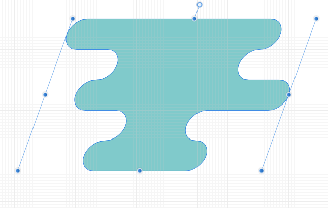
 Hello, I was wondering if within Affinity Designer is there a "Free transform tool" to allow perspective distort with shapes, this is something that can be done within illustrator where you can take two points and can move them together or further apart with equal distance like the example below. You can kinda do this with the "Corner" tool set to straight but this is set to only one angle when perspective distort can change the angle. Thank you for your time and I hope you have a great day.
- 317 replies
-
- 14
-
-
- mac
- free transform tool
- (and 5 more)
-
 I would like to distort some portrait images in a kinda weird-ish way. The way I have it in my mind is as if the images were melting, you know like candle wax running down the side of a bottle or like ink which has come into contact with water and the image is partially distorted. Is this possible and if so what is the best way to go about it? ~ Much'O Thanks in advance.
 -
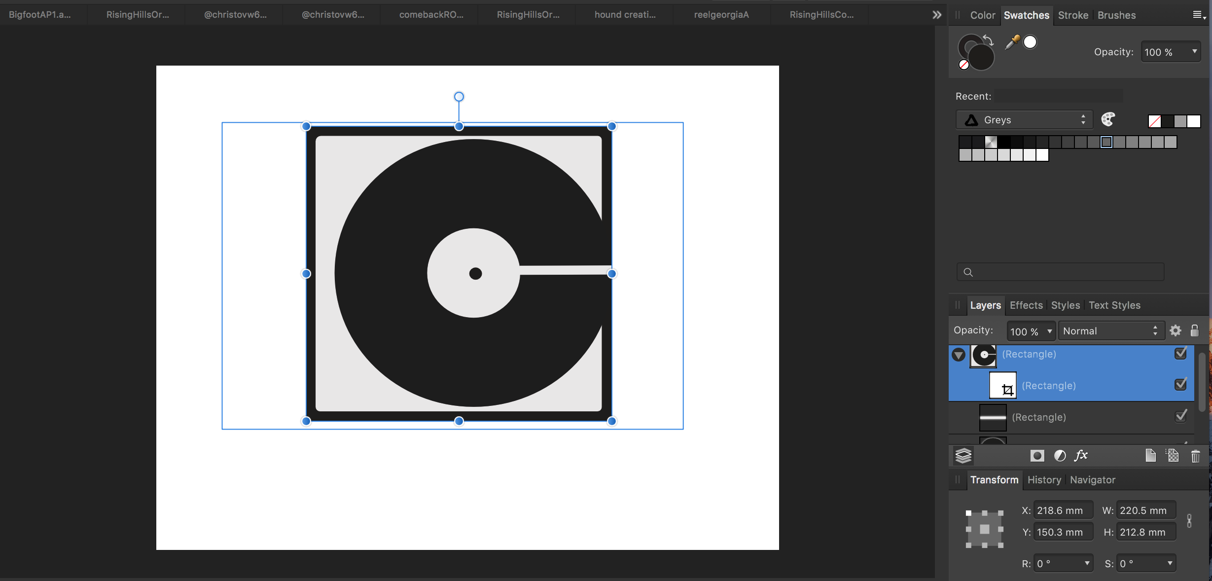
 I have traced logo in Affinity Designer. I have object open book cover. I want simply put logo adjusted to cover. Idea ilustrate sample picture: On X and Y axis is simple - click on object, put value in navigator or move by Move Tool [V]. Using small circle I can rotate object. I want distort object to achieve effect similar to circle with shape on the left before text Dodo Case - it is what I mean by adjust in Z axis. Normally I would use distort or mesh tool but in AD is not available. I try select object and use Node Tool [A] to make this, but I'm not very happy with result. I have logo with man with a lot of points and adjusting this is quite troublesome (I have two groups - first is a complicated shape and second are bunch of simple circles). I try use S in Navigation to shear object and is at this time the best option for me. So then only available option is use Node Tool or S in navigation to achieve adjustation on Z axis or maybe can you sugest me another and better aproach?
 -
 Hi guys, I'm having trouble to find a way to fit an image to another's perspective. In photoshop I use the free transform tool. Unfortunately I wasn't able to find something similar here on the iPad. The closest to it is the Shear/Rotation, but that's not flexible enough for my needs. Can anyone please help me? Thank you
 -
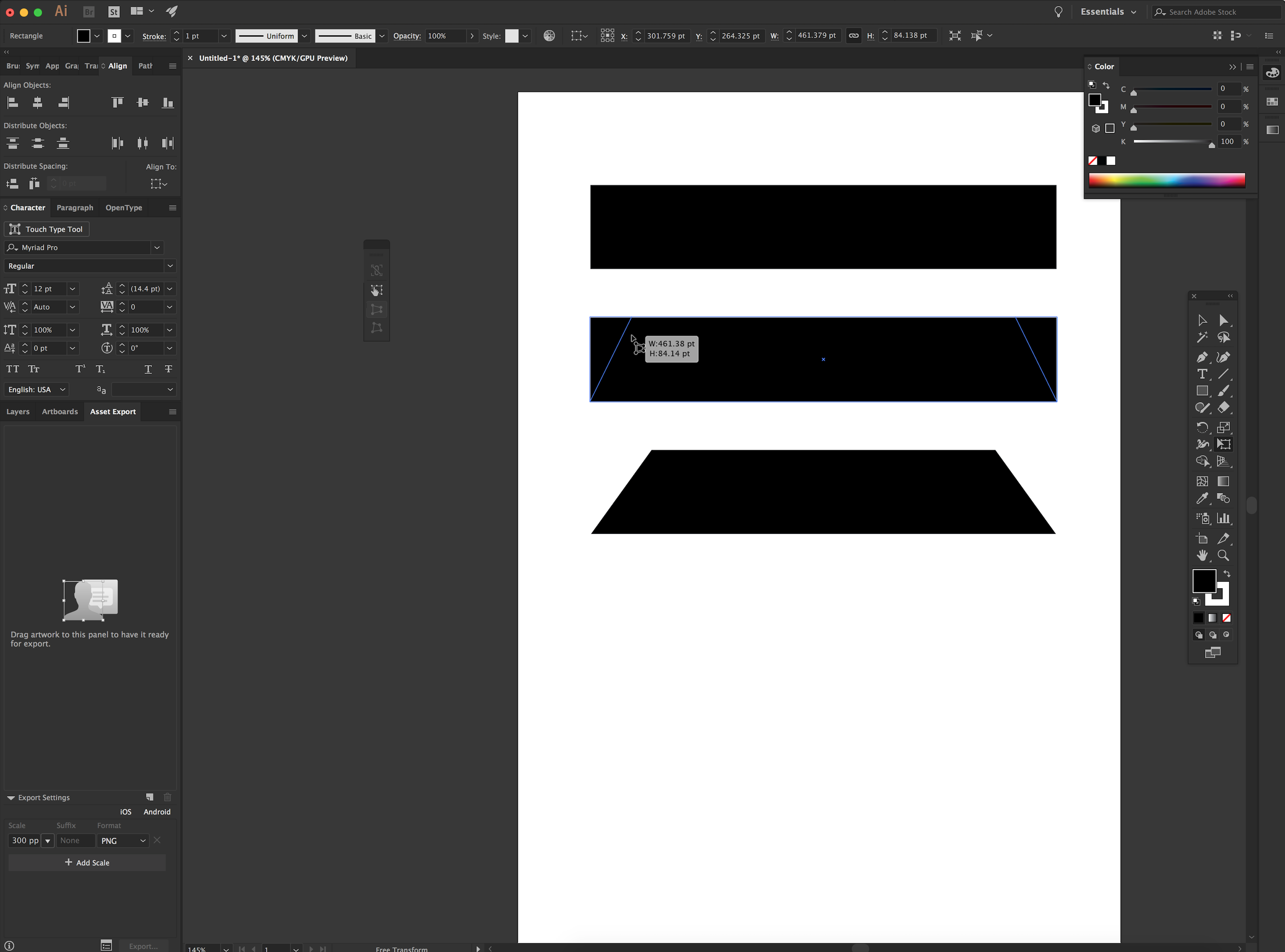
 'morning guys/gals, 2 quick questions please (and thanks): 1) in the image below (thumbnail and file attached) you will see a logo image that was originally on a black rectangular background. I cropped the L and R sides to get rid of portions of the background so as to create an even-ish border. How can I get rid of the still-remaining blue lines outlining the original boundaries of said black rectangle background? ...and, 2) in order to distort/stretch this image (logo portion), don't I simply 'convert to curves' the grouped layers then click/drag whichever node I'd like to 'pull' on? My goal is to be able to manipulate the image by independently move nodes to create perspective changes in some cases, or make the image look curved in other cases (as if on a cylindrical surface such as a telephone pole, etc). Does the image/layers need to first be flattened. Big thanks from a newbie! -Christo CVlogoBlueCropLines.afdesign
-
Recently I face a problem where I had to put a text on to a perspective product in a circular form. I was unable to do that and had to get it done from AI and shift to AD. I also found that there are no text wrap options into this.
-
 As one of the 30+ year users of Fireworks who refuses to use clunky Adobe products because it kills my billing time, I am coming to appreciate the speed and power of Affinity, BUT, for a company that did so much that's thought out so well, the one thing that Fireworks had that I miss would be the freeform distort tool. Effectively you could grab any corner and tweak the box for images or text and stretch or flatten it to any perspective. The best part was that you didn't have to "rasterize" the text and lose the ability to change it for size, type, color, etc. as you were manipulating it. For doing everything from creating quick shadows of something to mimicking the Star Wars disappearing text crawl in a graphic, it worked religiously well and quickly. Speed's name of the game when you compete with others not only on your talent, but billing by the hour, and flipping more jobs in an hour. This would be most handy. Thank you.
 -
 Does anybody know how one can make a page curl effect similar to Photoshop? I can see the functions "lattice distortion" and "perspective" but couldn't manage to create a page curl effect though. Thanks for your help! Kind regards, Isabelle
 -
 Is there a way to distort vector artwork along a defined shape? Is there a way to simulate tilting it backward into space, skew or warp the artwork?
 -
I am sure we could all go on listing “filters I would like to see” and never reach the end. It’s so personal. So I am going to be very simple and suggest a simple modification to an existing one. Cylindrical Distortion is one simple filter I really miss. And there really is no substitute for this in AP. Since this is (I think) simply a one axis spherical distortion could this not be included in the Spherical distort with a simple one axis/two axis checkbox? Far better still would be separate pairs of X and Y sliders for Intensity and Radius enabling any variation of spherical, elliptical or cylindrical. You could have a Lock/Unlock for using the axes separately or together.
-
 I've been playing with the Distort Filters and I can't see any change at all after applying the Deform filter. Tried every possible combination of adjustments and an A-B comparison of my layers before and after applying shows no difference. What am I missing?
 -
 Hi, is there a way to distort an object using an envelope, and/or some kind of perspective tool? I’ve just got to something that would benefit from that, and I can’t find a tool for it. I rather suspect that it’s not there - if it isn’t (and isn’t on the To Do List), can I put in a request for it to be added? Thanks.
 -
 Hey guys - I wanted to know how to do perspective in AD so I can keep it vector. Any quick and dirty tricks will be much appreciated. Here's a screenshot of what I'm trying to do. Thanks, Marc
-
It would be super awesome if more was made of distorting shapes. At the moment if you hoover the mouse over the protruding centre line at the top of any shape and wait, you get a little icon which is two arrows pointing in either direction, you can click and drag this to skew the shape a little bit. But they you need to keep rotating the item then turning it a bit if you want to adjust it and it can be a bit of a pain. It would be great if there was a distortion menu which allowed you to just selected pre-made angles for which your shape could distort too, so for example isometric left, isometric right, 45 degrees etc.. and if then you can add advance alteration like changing the percentage of the skew and the manually pick the direction that would be perfect! Really awesome work on the software so far I use it everyday now!