Search the Community
Showing results for tags 'Distort'.
-
 I am making some pattern that will be cut with a laser. This means that I have to plan the paths for the cuts by using vectors. I need to cut the whole edge of a piece (curvy) on a zig zag so the curves keep some stability once cut, but I can't finde a way to turn my smooth lines into zig zag ones.
 -

PDF Export not matching Designer file - warp problem?
Bryce posted a topic in V2 Bugs found on macOS
Here is what my V2 Designer file is supposed to look like: Here is what it exports like: The only way to get it to work is to have the PDF rasterize everything - including text.
-
 Hi, I want to procedurally distort linked files (topographic maps) like in this example below: The reason it needs to be procedural is because I still have to change line weights and/ or elements on the various maps. I was planning to distort linked files using the new Vector Warp feature in Designer, but it doesn't accept linked files, see feature request: I then moved over to Photo, tried the live projections, but unfortunately, the live projection grid widget does not correspond to the layer's bounding box. I then used the Perspective tool, which is close to what I want, but it converts my file to a pixel layer. This means it is destructive. Are there any other options?
-
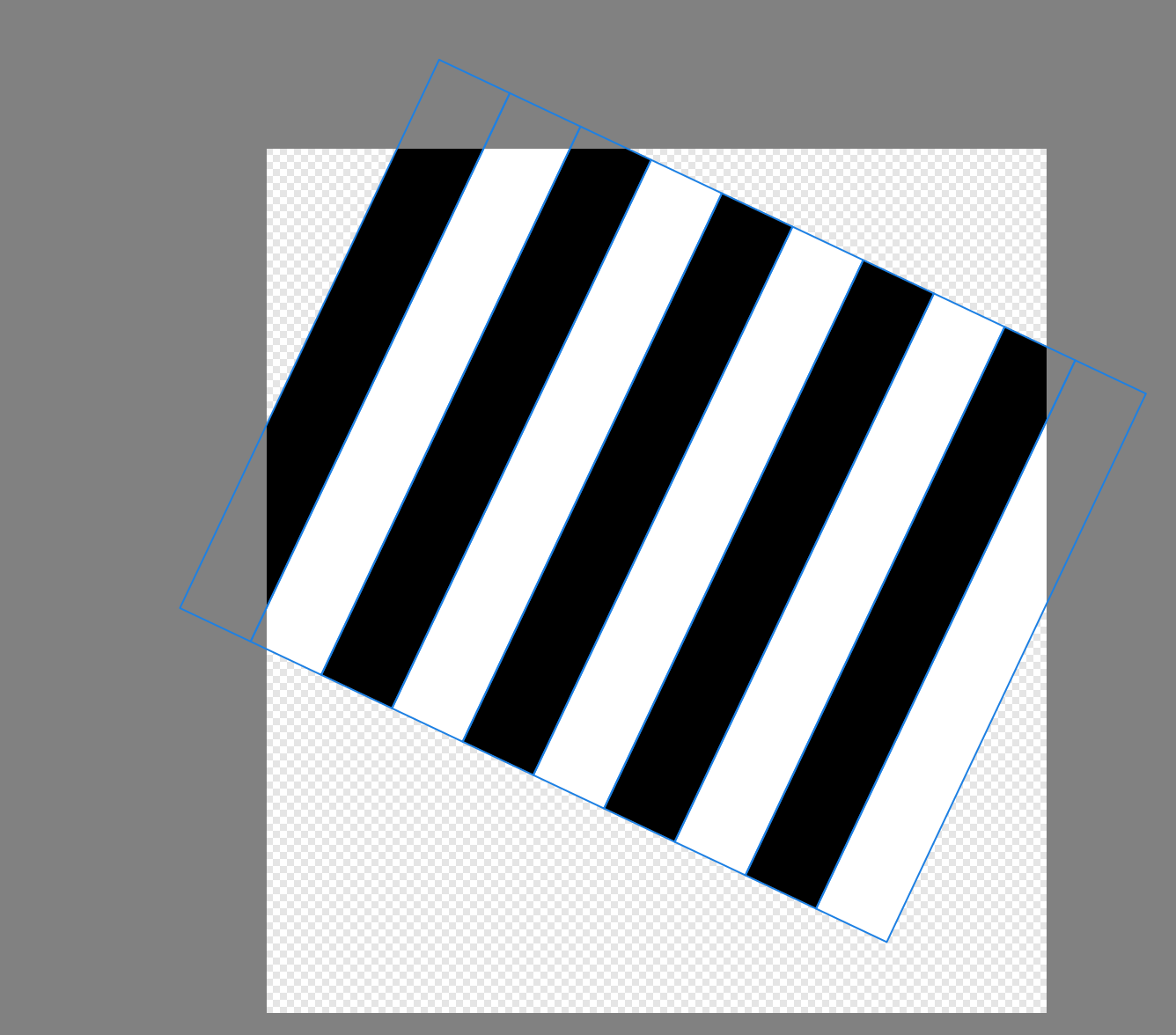
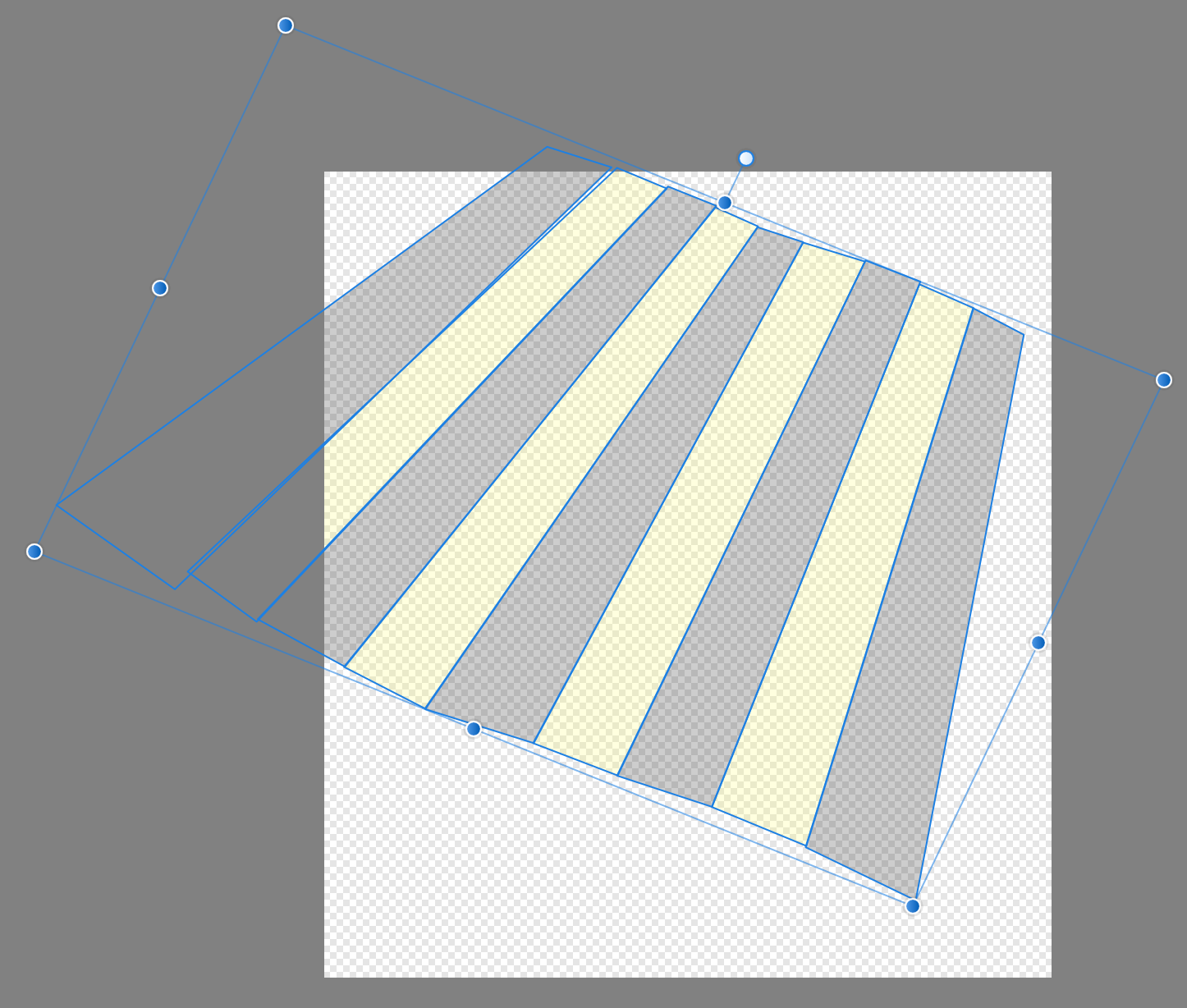
 Feature Request: Ability to distort/skew perspective of curves in Affinity Designer. I drew a rectangle shape, converted it to curves, and duplicated it repeatedly into stripes. I would next like to distort, skew, stretch the perspective. But I don’t see how with the current set of tools. Best I can discern is to grab nodes and randomly pull them where they look close enough. But this is time-intensive and imperfect. I also tried drawing trapezoid shapes, but their controls seem even less precise. I asked in the support board how better to do it, and I was told there is no way (https://forum.affinity.serif.com/index.php?/topic/166065-how-to-distortskew-perspective-of-curves-in-affinity-designer/). Thank you.
-
I drew a rectangle shape, converted it to curves, and duplicated it repeatedly into stripes. I would next like to distort, skew, stretch the perspective. But I don’t see how. Best I can discern is to grab nodes and randomly pull them where they look close enough. But this is time-intensive and imperfect. Is there something easier I’m missing? I also tried drawing trapezoid shapes, but their controls seem even less precise. I searched but found several posts from several years ago asking for this and being told it didn’t exist as a feature yet. Affinity Designer version 1.10.5 on macOS. Thank you.
-
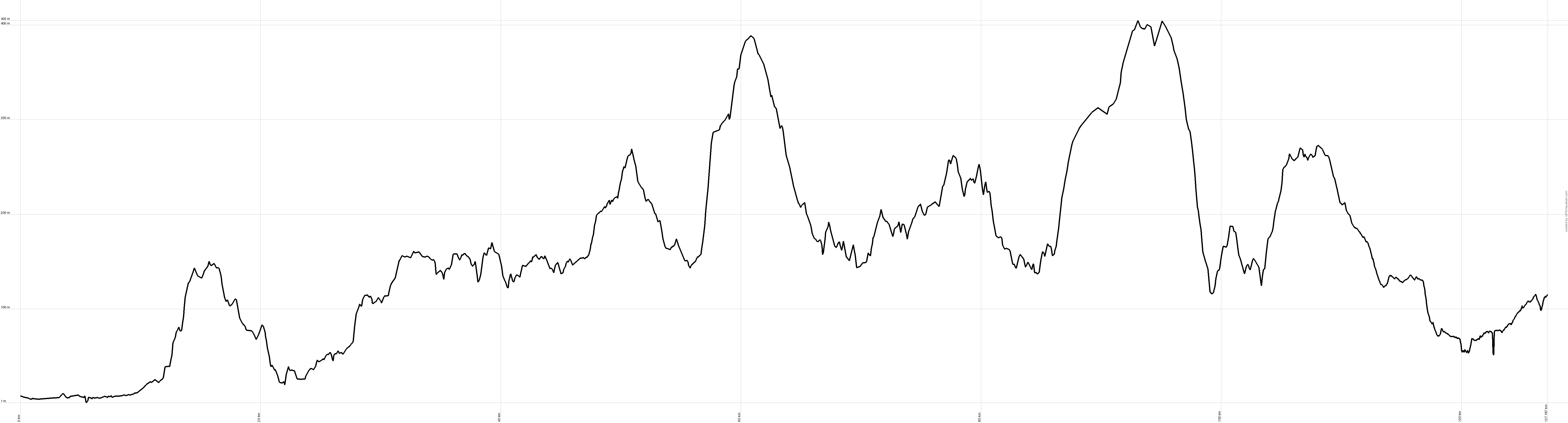
 Hi Affinity Community, I am looking to create a circular visual with text and a profile (which shows elevation and distance) that curves around the edge. I have been looking at this thread: https://forum.affinity.serif.com/index.php?/topic/131951-text-alignment-in-shapes/&tab=comments#comment-726530 And have found useful info for setting out and aligning text. I am also looking to warp this rectangular image onto the outside of the circle. I'd want to adjust the scale of it, so would transforming into a donut would be the best way to manipulate it? These would eventually go around the whole perimeter, I could either stick them together and warp one image, or ideally go around the segments adding another elevation profile. One elevation profile is attached (I have 12 of these) and an example of the final image I am aiming for. I'm using Affinity Photo. Thanks.
-
 Hi guys, some of you might be wondering if there's a skew or distort feature in Affinity Photo. So in this video, I will show you how to use and where you can find Skew, Distort, & Perspective feature in Affinity Photo. I hope you enjoy watching this video, thank you!
- 2 replies
-
- 2
-

-
- affinity photo
- tutorials
- (and 5 more)
-
 Please add an Envelope Distort Feature, A function that lets you warp text and shape paths
 -
 When using Filter > Distort > Shear, I can move the nodes by dragging or using the arrow keys. However, it would be good if I could enter formulae to describe how a node moves. For many purposes, this would be much more convenient than using Filter > Distort> Equations (which can do the trick). I have reported in the Bugs forum that moving the nodes with the arrow keys has a bug. Thanks to @MxHeppa who raised this problem in my thread on Warping Test onto a Wave. John
 -
 I don’t get it! From the reviews I’ve read before getting the Affinity Designer for the iPad, I was under the impression that this is the best design app ever! How does the best design app ever not have a Free Transform tool or options?! I’m totally frustrated and wasting a lot of time to figure this out, because I simply can’t imagine that a “design” app doesn’t allow me to distort an image. And the idea that I have to buy another app and add to the work and time, just to transform a simple image, and disrupt my work flow! Could someone explain how this happened? Because I’m regretting buying the app with every passing day.
 -
 I've long been waiting for warp/distort tool but it hasn't been implemented yet. It's time to add it to the current version or version 1.9.
- 7 replies
-
- 1
-
-
- affinity designer
- warp
- (and 1 more)
-
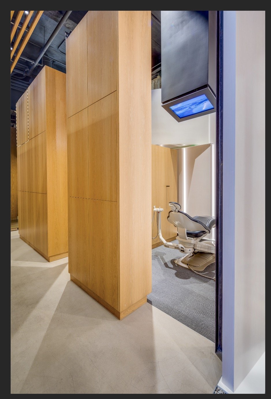
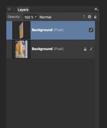
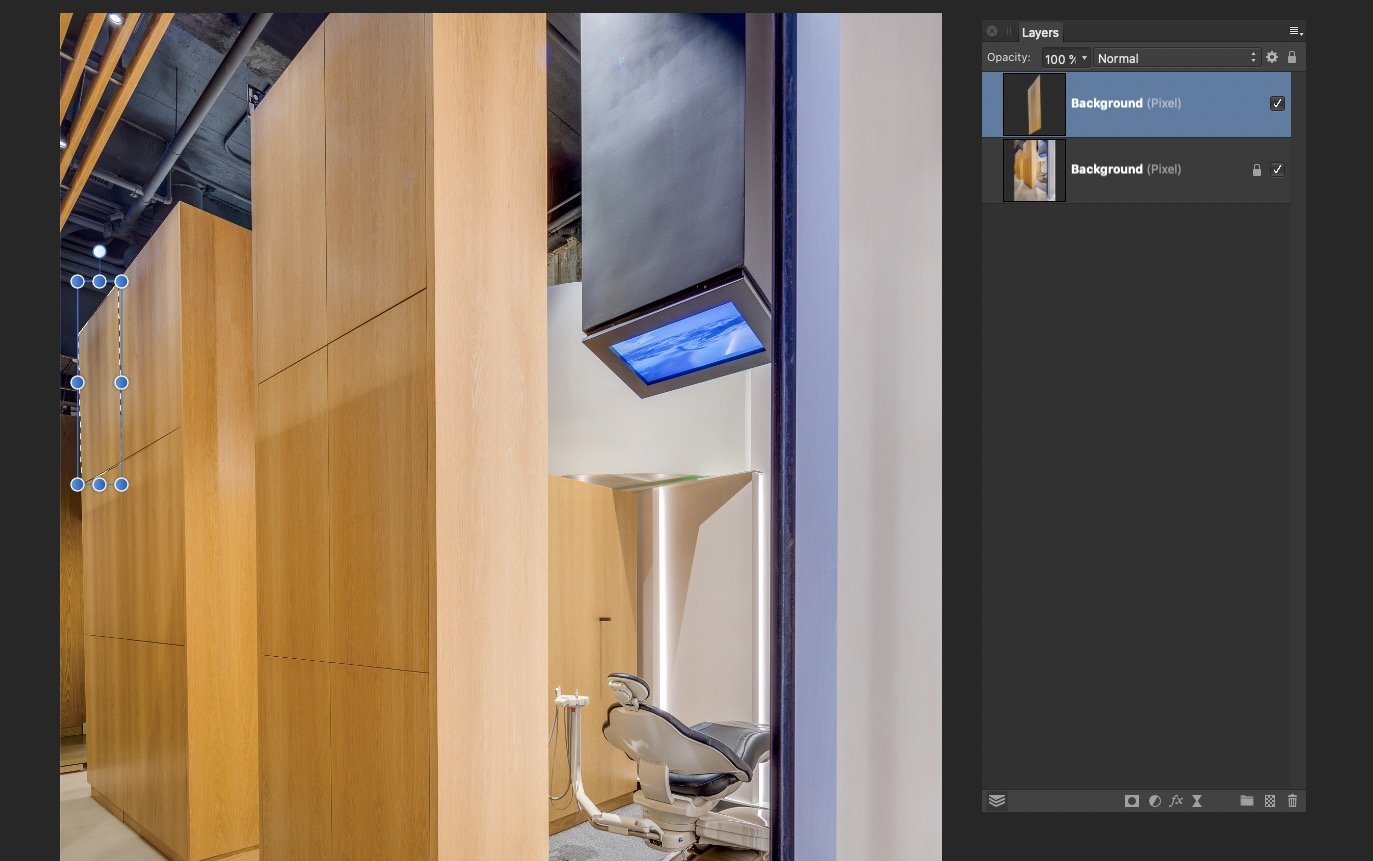
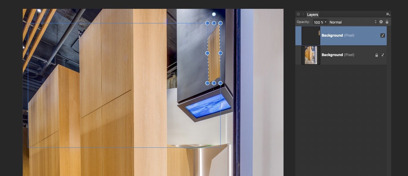
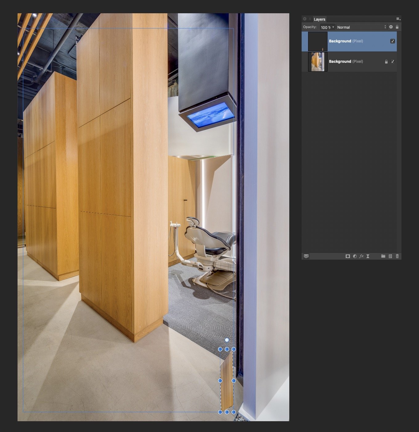
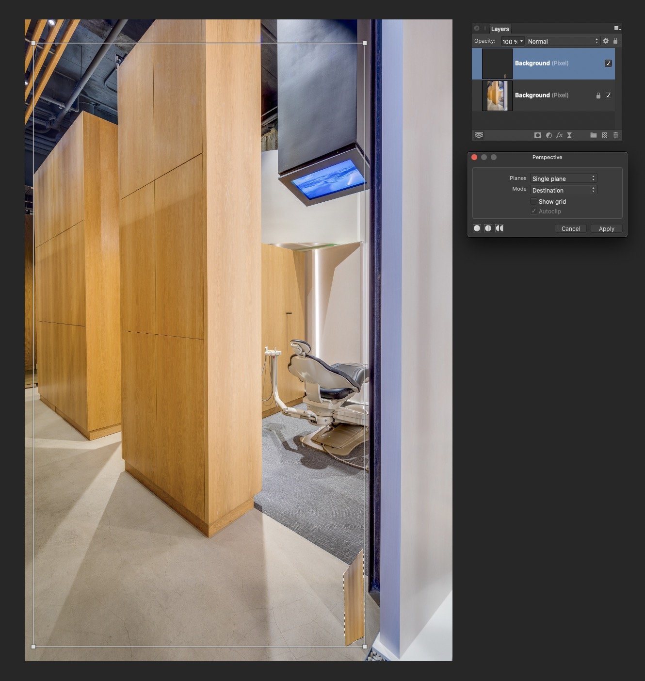
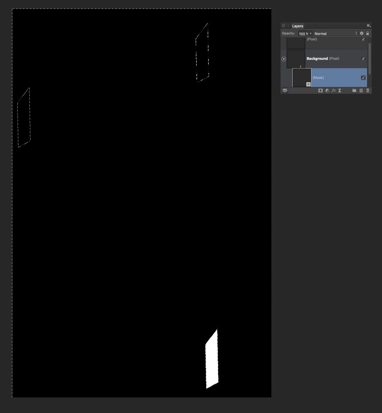
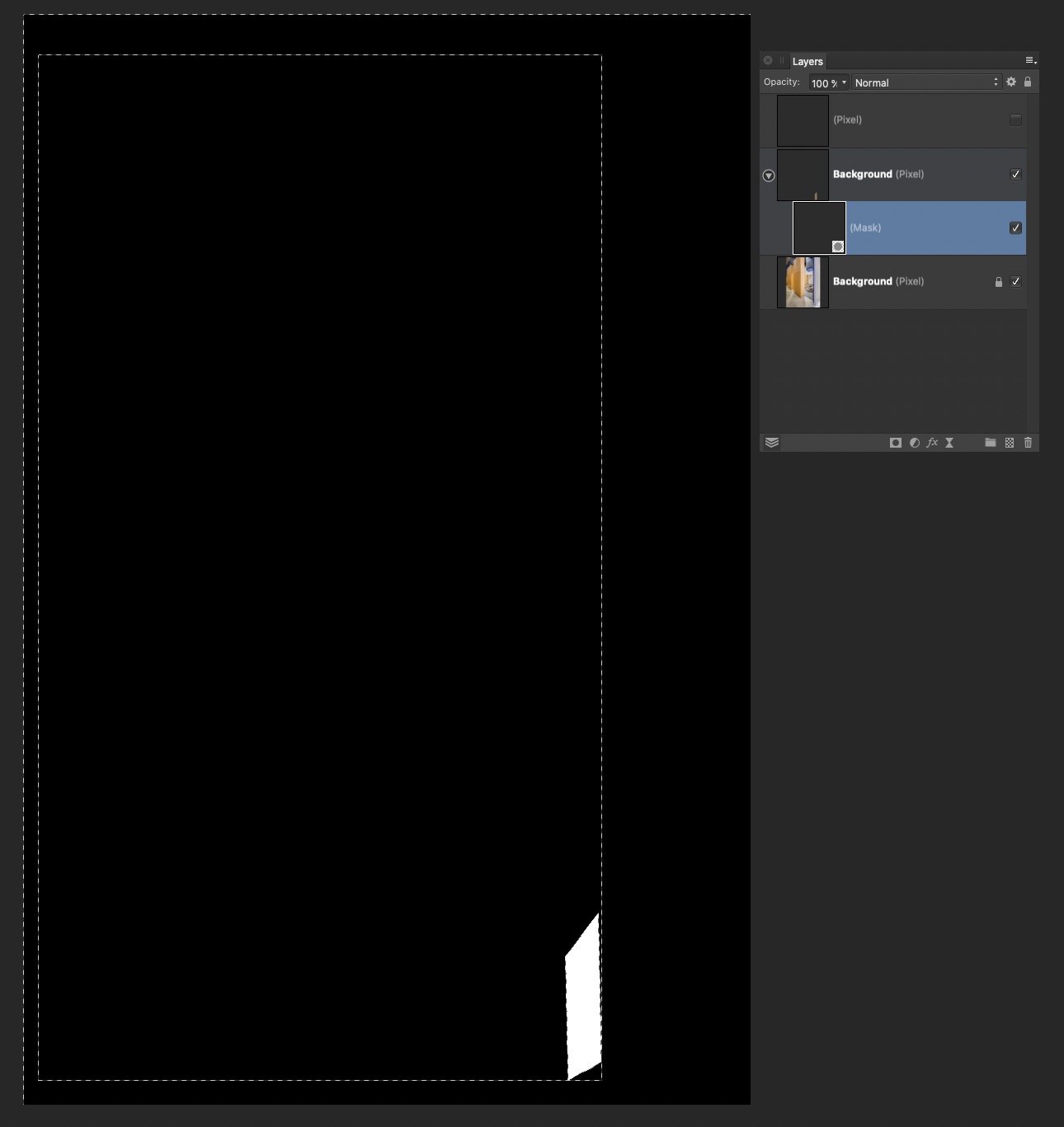
 I have a substantial issue I am hoping to resolve. I do a lot of architectural retouching, and I often copy-paste small elements all over an image, often from one side to another. I always have to distort/perspective/warp these objects to make them match up. Every time I move or distort an object on a layer, the layer increases in size by the amount of change. So if I copy/paste a region of pixels, then move it across the image to the other side, Affinity thinks the now transparent pixels somehow still have content, and increases the layer size accordingly. If I Command-Click the layer, the selection edges include the now empty pixels. Also if I try to use a distort filter, the handles encompass the entire expanded layer. This makes it nearly impossible to do accurate distortion. I have tried and tried to isolate just the actual pixel content, up to and including selecting the non-transparent pixels and creating a new document. Affinity refuses to accept that the transparent pixels are empty, and includes them in the entire operation. So if I move a 100x100 pixel selection across the image by 4000 pixels, I now have a 4000 pixel layer, that Affinity refuses to trim or crop. Even after I carefully select everything in the mask layer except the white, hit delete, and Command-click the layer again, it still shows the selection bounds including every other location where I moved the content.
-
 Let’s see if I can explain what I’m trying to do in Affinity Photo. I have some photos which I got using a scanner app on the iPhone. Some of them ended up distorted, becoming too narrow. What I want to do is to correct that manually, not by guessing what the correct width should be and inserting digits, but simply to be able to grab a handle/node and stretch the photo until it looks right. You can do that with shapes if you convert them to curves, at least in Designer, but so far I haven’t found how to do it in Photo, manually, by just stretching the photo until the width looks right. is there a way to do it?
 -
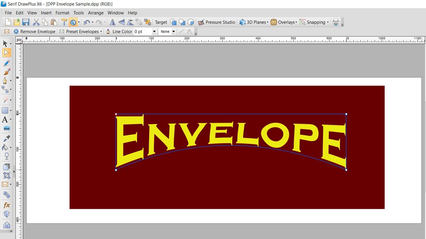
Why is there NO "Envelope" or "Warp" tool in Designer?! It's absurd! Envelope was there in Serif DrawPlus. Creating arc'd text (not on a path) is a BASIC text modification. With all the complex things Designer can do, why is this missing? This has been requested for years!
-
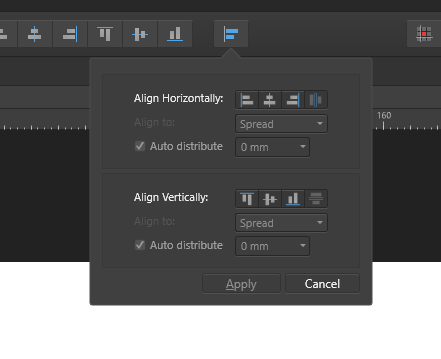
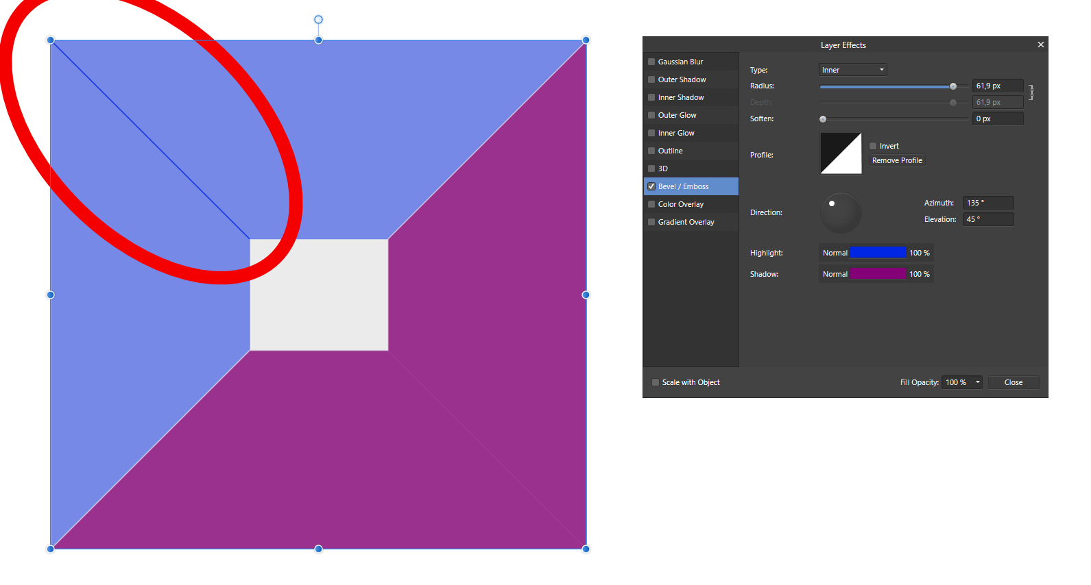
 Bug 1: Embedding a document into another one and rotating it doesn't rotate the light sources. Reported this for the previous version already, original report: Bug 2: Aligning to masked object behaves differently from aligning to masked curve I reported this here already: Bug 3: Alignment drop down menu can not be moved to a panel Feature Request: Alignment drop down menu can not be moved to a panel Bug 3: Copying the style of one object to another changes the settings. Steps to reproduce: a) create a rectangle, size doesn't matter b) right click it -> Layer effects -> "Bevel/Emboss" -> slide the radius to "20px", other settings do not matter. -> apply style with "close" c) select the rectangle and press CTRL+C to copy it to clipboard. d) create a 2nd rectangle of different size (make it much bigger to have a more visible effect) e) press CTRL+SHIFT+V to paste the small rectangles style f) check the settings of the new rectangle: right click -> Layer effects -> "Bevel/Emboss". The radius is now something totally different from the original "20px". This bug also happens to other layer effects and the "Scale with object" setting does not have an impact. Fun fact: If the 2nd rectangle is created by copying the 2st rectangle right after step (a), then resizing it and going through the rest of the steps (that means adding some layer effects to the 1st rectangle, selecting it, CTRL+C, selecting the 2nd rectangle, CTRL+SHIFT+V), the layer effects stay in tact! That's super weird to me! Bug 4: Weird rendering artifact for sharp Bevel Applying a sharp bevel/emboss with a 45deg angel light source (that's not too uncommon ... 🙄) causes a weird dark line on the edge. It should not be there, it should all be uniform. Same for the white line on the opposite side. Final notes. Ok, that's the bugs I found so far. Oh and any news on a vector envelope/perpective/distort or scissors tool? I'm just asking for a friend ... Naja, non the less I like seeing you guys working to improve the software. Keep it up.
-
 I – surprisingly – couldn't find anything substantial on this topic here, so I'll start a new one... (and I hope I haven't overlooked some feature of the app that actually would have made this request unnecessary) As it is, I dearly miss something like Photoshops's "Free Transform" in Affinity Photo. In AP the whole transformation business is – to me – rather clumsy and really not ergonomic at all. It can be really tedious to sort of "model" a pixel selection to certain shape by using a combination of scaling, rotating, shearing and distorting (free or in perspective). In Photoshop – which I'd really want to give up in favour of AP – it's all under your fingertips: just press CMD-T and with that context-menu "Free Transform" provides, you can do almost ANYTHING to your pixel selection (either including the selected pixels or not). It's all there under the right mouse button (or just a keyboard shortcut away if you're using a graphics tablet with a pencil) and you can go between ALL the different types of transformations I mentioned above without once returning to the menu bar or some palette. And when you're ready, you hit ENTER and you're done. This is simple, intuitive and just ergonomic and it's been there for years and years. With AP complex transforming is just annoying and unpleasant work to me. I my opinion it's really a strange idea to "hide" transformation options like shear and distort in the "Filters" menu – as these very ARE basic transformations and should be accessible (at least) from the "Transform" panel, if not – as in Photoshop – actually from a context menu on screen right next to the selection you're working on. I personally think it is quite an unreasonable demand in AP that – e.g. – for shearing you have to pull at some abstract lines in an extra panel far from the actual selection on the screen. If this could be adressed some time soon, working in AP would be so much more pleasant for me.
-
 The video is dedicated to the topic "How to Transform a Photo into a Brick Wall Portrait" in Affinity Photo and those people, who want to learn this very easily with step by step.
-
- 4
-
-
- brickwall portrait
- affinity
- (and 5 more)
-
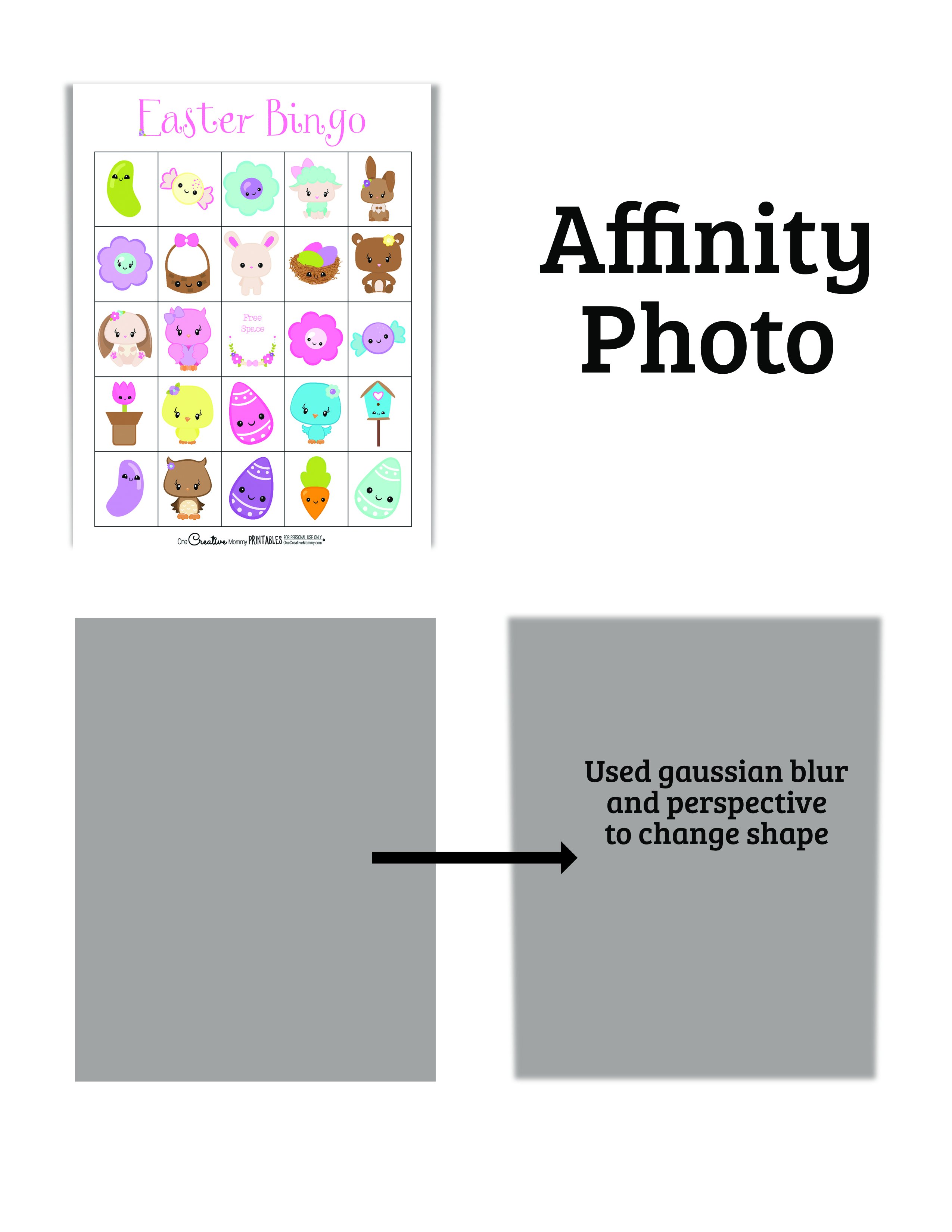
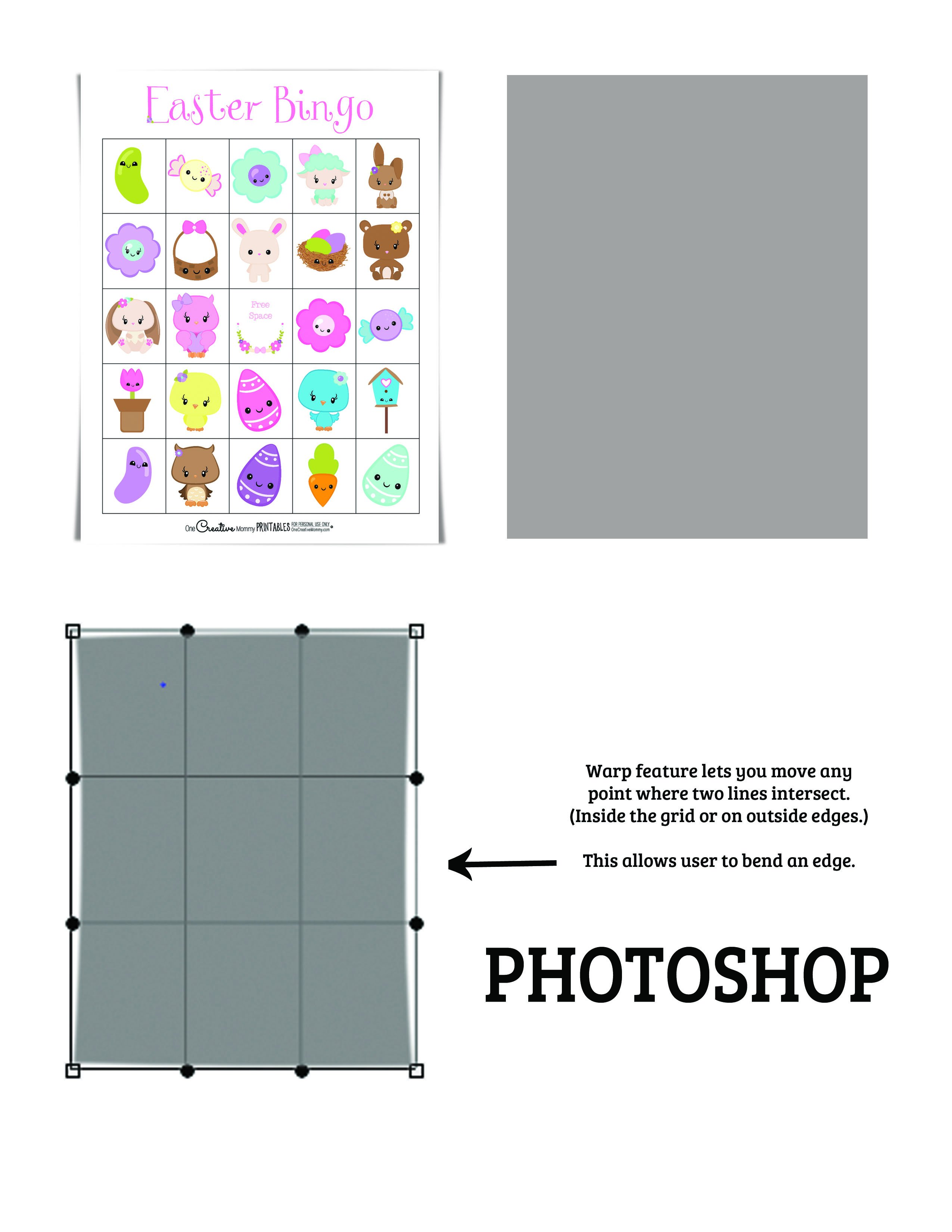
Adobe photoshop has a feature called warp that I would love to see in Affinity Photo. When you click on the warp feature, it looks similar to the perspective feature in Photo (with the grid over the image). The difference with warp is that instead of only the four spots (points that can be dragged) on the four corners, each intersection of the grid is a moveable point. This is particularly useful when trying to make shadows that make papers or cards look curled. The warp feature allows the user to bend a shadow in the center of a side instead of just pulling out the corners. I'll attach an image to show you what I mean.
-
Can you guys please port over the distort feature from Serif DrawPlus or PagePlus into Publisher? This has been announced 5 years ago to be on the roadmap for Designer and still is not there. Today, I am using the Distort from PagePlus (=2015) or CorelDraw7 (=1995) to do this and copying the results back into Designer/Publisher. Quite embarrassing.
-
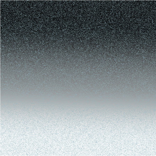
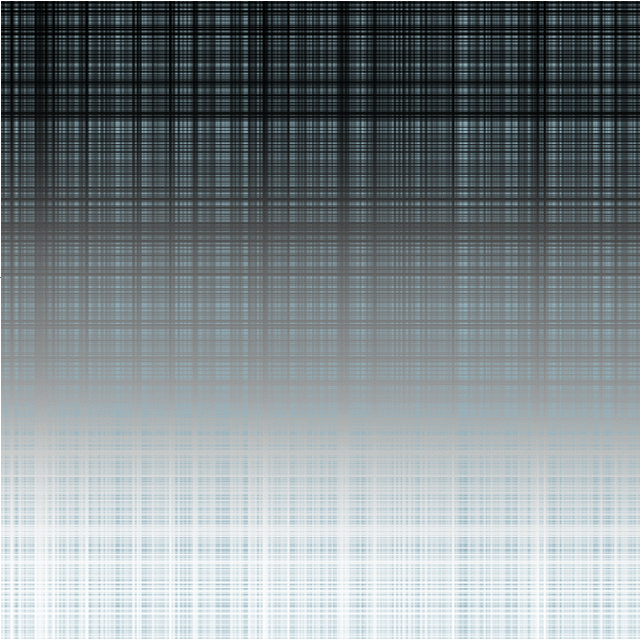
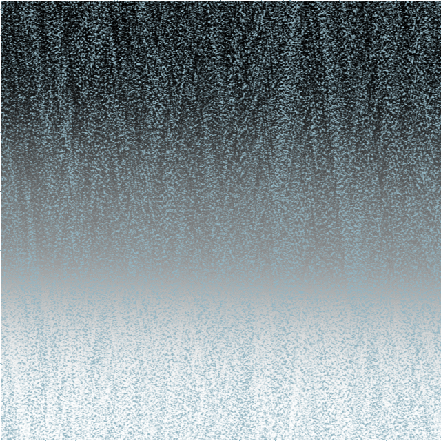
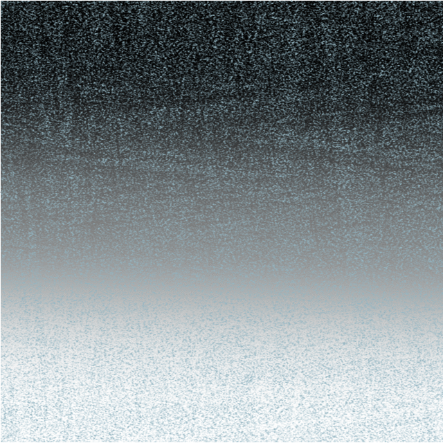
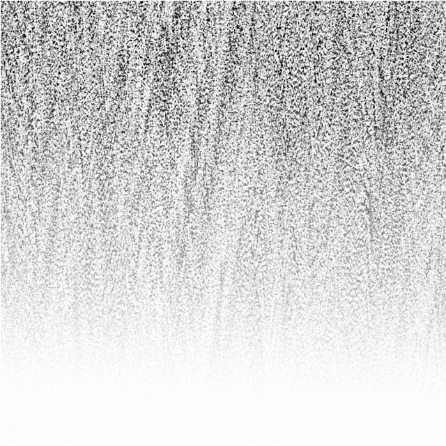
WARNING: for the technically-minded only! The Noise functions in the Filters > Distort> Equations facility are supposed to add (unspecified) noise to an image. The only description I can find of this is in the video by James Ritson. He first duplcates the layer and then uses either noise(x*y)*a or noise4(x*y)*a in his equation. This produces a grain-like effect over his image. The documentation for equations is limited. There is the Expressions for field input in the Help system which gives, under : Noise(seed/x,y), an explanation: Generate 1D noise either from a seed or based on X/Y input with similar definitions for noise2, noise3 and noise4. James uses both the noise and the noise4 functions. In his video he is using the single seed parameter x*y, with the magnitude controlled by the a parameter. I have been experimenting with these noise functions and present here my findings Although the Expressions for field input names the functions Noise ... Noise4, with a capital letter, these will not work. You need to use a lower case n for noise. The function noise2 has no effect. The functions noise, noise3 and noise4 seem to produce identical visible results. The histograms are also identical. Using a single parameter, either a simple number, or an expression such as x*y, has no visible effect unless the Full option is selected in the Extend Mode at the bottom. When using two parameters, they need to be different in the x and y axes to produce any visible result. Multiplying the parameters by a number, such as noise(10x,10y), has no visible effect. I show here the effect of varying these parameters on a simple gradient field: Here is the effect of x=noise(x,y) and y=noise(y,x): The results for noise3 and noise4 are identical, as are noise(3x,3y) etc as are the histograms. If the parameters are the same, say x=noise(x,x) and y=noise(y,y) You get a very different effect: Almost like a tartan effect. If the noise functions are the same in both x and y such as x=noise(x,y) and y=noise(x,y), it works OK, but if you use x=noise(y,x) and y=noise(y,x) there is no visible effect unless you select Full: The difference between using Zero and Full in the Extend Mode at the bottom is subtle. Using Full seems to convert the image into a monochrome effect with the background invisible. However, the noise is based on the luminance of the background. Just for comparison, I append here the effect of the effect of the Add Noise filter (Filter > Noise > Add Noise...): You can control the intensity of the noise here, which is more than you can in any of the noise functions I have described. In conclusion, I would recommend that if you want noise, then use the Filter > Noise > Add Noise... option above until such time as the devs at Serif come up with a more understandable noise function in Equations. Having said that I am not holding my breath on this. Using noise in equations is probably a minority pursuit amongst users and the Add Noise filter is much easier. John
-
 I'm currently test driving all of the Affinity products in hopes of leaving Adobe's Creative Cloud, but am coming up just a little short on some key tool necessities. The biggest hole I can see is the ability to distort or free transform vector nodes, whole objects or outlined text (curves). This is a tutorial on creating 'curved' text using 'free transform' tools in Illustrator from 2000: http://www.balloontales.com/curved-type/ Or selective scaling when nodes are selected. Here's an example of the function; keep in mind this isn't about WHAT is being created, it's the 'how'. http://www.balloontales.com/tv-shape-balloon/ Just added functionality to node/vector manipulation and I can then say goodbye to Adobe Illustrator. If these functions already exist, can someone point the way to any related tutorials? Thanks! Good stuff so far; just need a few more tools to be GREAT stuff. G.
- 2 replies
-
- 5
-
-
- vector
- free transform
- (and 4 more)
-
 I'm sure its been asked a thousand times but is there any chance of a similar function to Inkscape's path effects being added to 1.7.0 << if it were to happen I would be more than happy to pay for the upgrade from 1.6 A very simple example is shown in this video: https://www.youtube.com/watch?v=aotGj9iJB4U
 -
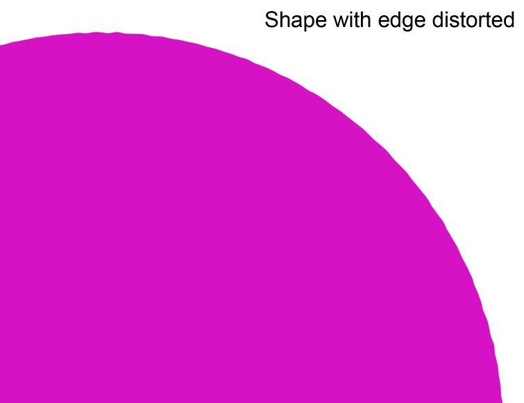
 I'm using Affinity Designer. Besides using a textured stroke or manually adjusting curves/nodes, is there another way to distort the edge of a shape? Pic below is similar to what I'd like to accomplish. I could possibly create a textured stroke to mimic this, but are there other ways or anything automatic? Thanks again!
-
 Oh dear ... seeing the amount of excellent stuff that has been created on the site, I'm almost embarrassed to ask my question. Almost. It's quite simple, really, but it's just about driving me mad. Imagine - Draw a rectangle to simulate a long banner which is going to hang from a wall, with three eylets, top & bottom. Superimpose text. Now, when a real banner is hung, it will distort and droop where it is unsupported - ie. in between the eyelets. The text, of course, will distort with the banner. How do I do that in Designer? I can get the banner background itself to do it (sort of), but how about the text? Can't find anything in the tutorials which would help. I just KNOW I'm going to feel foolish when I'm told, but, at the moment, I'm willing to risk it !! Oh - just in case you haven't already guessed, this is my first outing with Designer.
 -
This is an extension of my tutorial on Trigonometrical transformations using Filter > Distort > Equations. This one is focused on simulating flags waving in a light wind. Flags have an advantage in that they have a standard shape (width is twice the height). Edit: I have been told that this is not true. I stand corrected. To get the desired waving, I apply a sine transformation to each of the x and y-axes. The equations to apply are: x=(x+20*sin(360*y/h))/c-100*b y=y+a*(h/10)*sin(2*360*x/w)-(x/w)*h/10 I add a sideways sine wave to the x-axis as a function of the y-position. When the flag waves, the visual width is decreased, so I have added a parameter c which scales the width of the flag. The parameter b is an offset, since the left-hand corners of the flag can otherwise move outside the canvas. The y-axis also has a sine wave, depending on the x-position. The parameter a determines the magnitude of this sine wave. The final expression (-(x/w)*h/10) ensures that the fly (RHS in this case) is below the hoist (LHS here). (Definitions: hoist is the part next to the flagpole; fly is the part flying free.) Here is the UK Union Flag, plus a bit of extra space above and below to create room: And waving in the breeze: And here is a macro that implements these transformations: FlagWaving.afmacro And a macro library containing the single macro: FlagWaving.afmacros The parameters should appear when you run the macro. Parameter a controls the vertical wave; parameter b controls the horizontal offset; parameter c controls the overall horizontal scaling. This macro will not simulate a flag in too strong a wind, where the parts overlap! John