Search the Community
Showing results for tags 'Distort'.
-
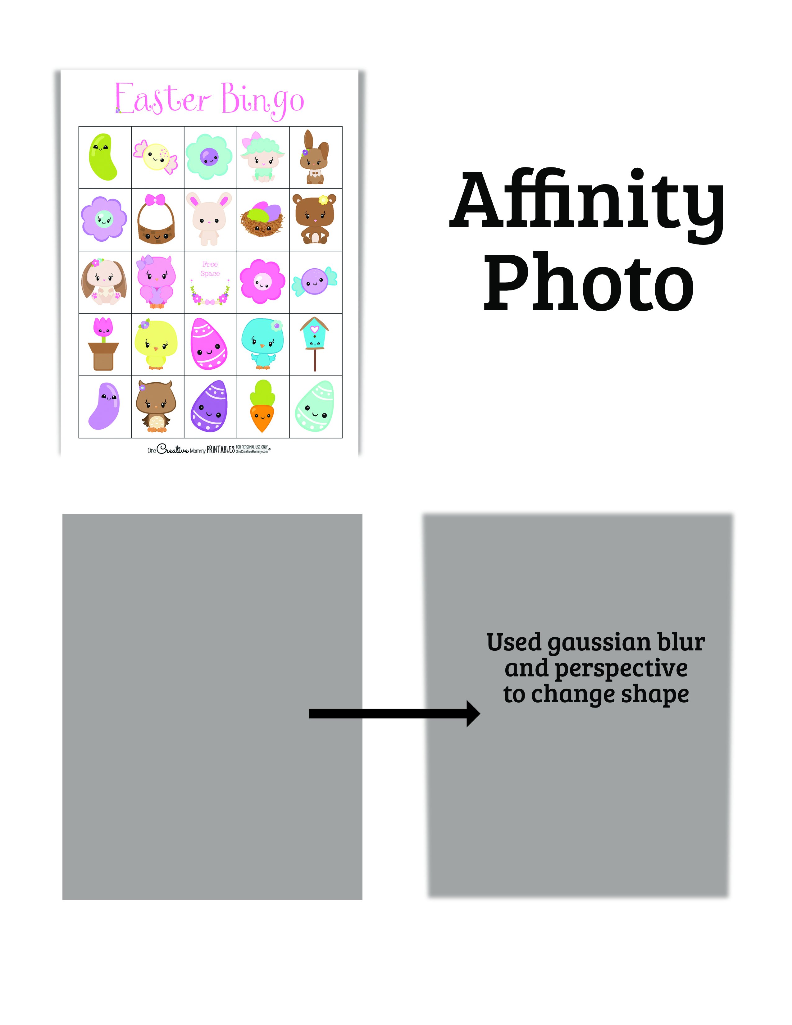
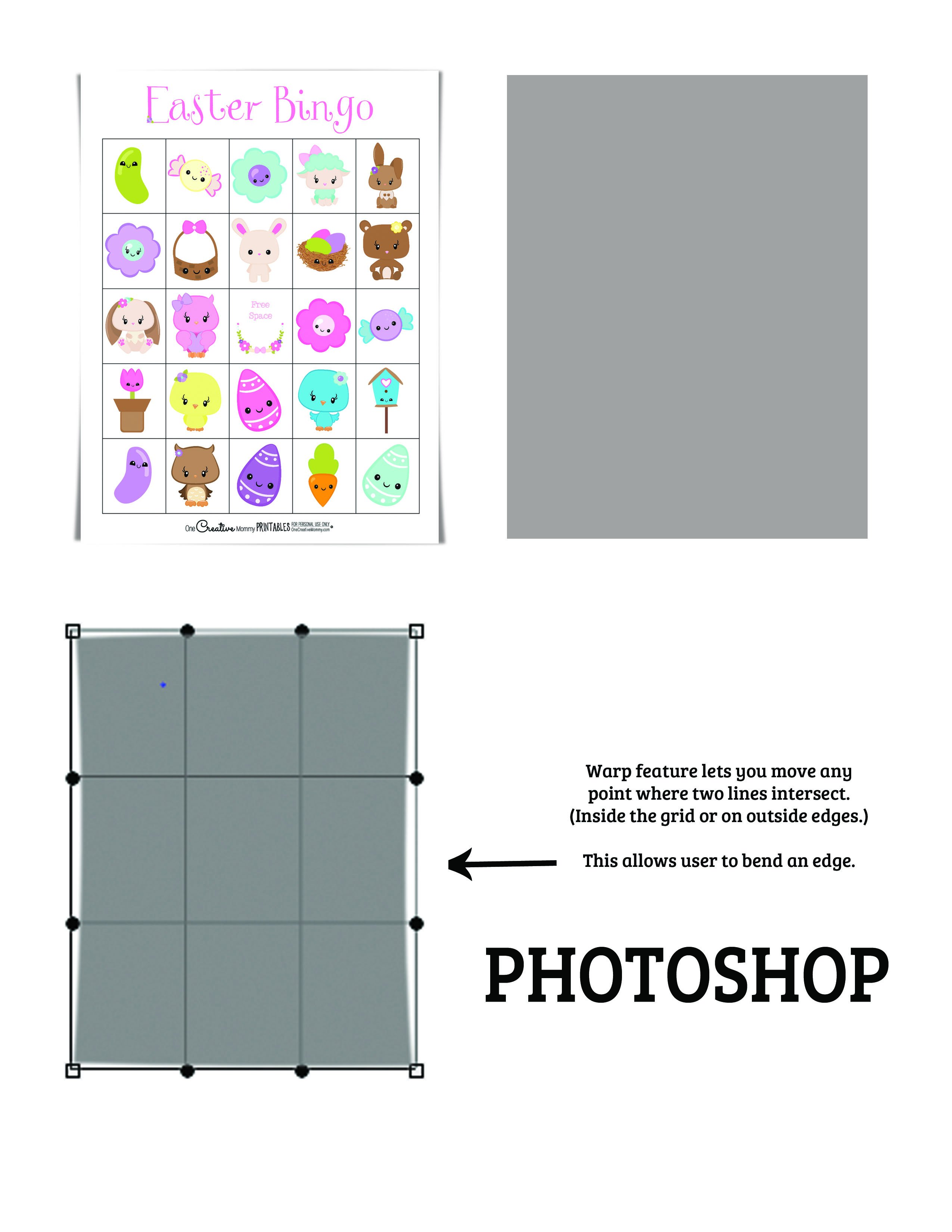
Adobe photoshop has a feature called warp that I would love to see in Affinity Photo. When you click on the warp feature, it looks similar to the perspective feature in Photo (with the grid over the image). The difference with warp is that instead of only the four spots (points that can be dragged) on the four corners, each intersection of the grid is a moveable point. This is particularly useful when trying to make shadows that make papers or cards look curled. The warp feature allows the user to bend a shadow in the center of a side instead of just pulling out the corners. I'll attach an image to show you what I mean.

-
 Hello, How to distort text like in Adobe Illustrator like a flag or arch ? How to distort horizontly or verticaly ? Thanks for advices.
- 5 replies
-
- 1
-

-
- artistic text
- designer
- (and 2 more)
-
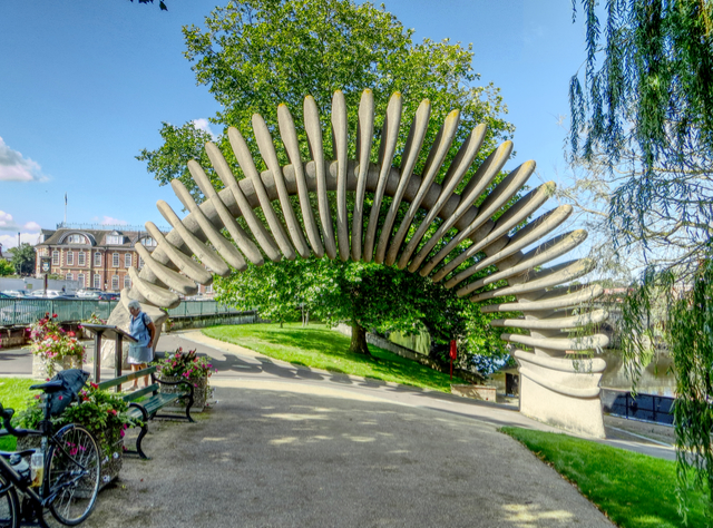
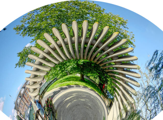
 Conversion of a rectangular image to polar co-ordinates using Equations is not straightforward. A major problem is that the origin of the rectangular Cartesian co-ordinates is the top left, whereas for a polar display, you would typically want the origin on the midline, probably near the bottom. The following equations assume that the origin is in the midline along the x-axis, and at or near the bottom on the y-axis. First select Filter > Distort > Equations and enter: x=w*atan((x-w/2)/(h/a-y))/100+w/2 y=h-sqrt((x-w/2)^2+(h-y)^2) The expression (x-w/2) displaces the horizontal origin to the centre, and the expression (h-y) displaces the vertical origin to the bottom. In the first formula, for x, there is a parameter a, which allows you to scale the polar transformation; reducing the parameter a stretches the image around the circle. The 100 is an arbitrary scaling parameter which seems to work. The expression +w/2 at the end re-centres the image. This seems to be necessary, but I am not sure why. I would have expected to deduct w/2 rather than add it! Here is an original image of the Quantum Leap statue in Shrewsbury: With this transform using the default parameter a, this produces a quadrant. And with the parameter set to approximately 0.6: Here is the Macro: PolarQuadrant.afmacro The first thing the macro does is to unlock the image. I tend to do this automatically in macros. It is probably unnecessary. I ought to be able to give the adjustable parameter a, a name, but I have not been able to do this. John
-
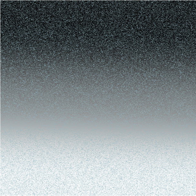
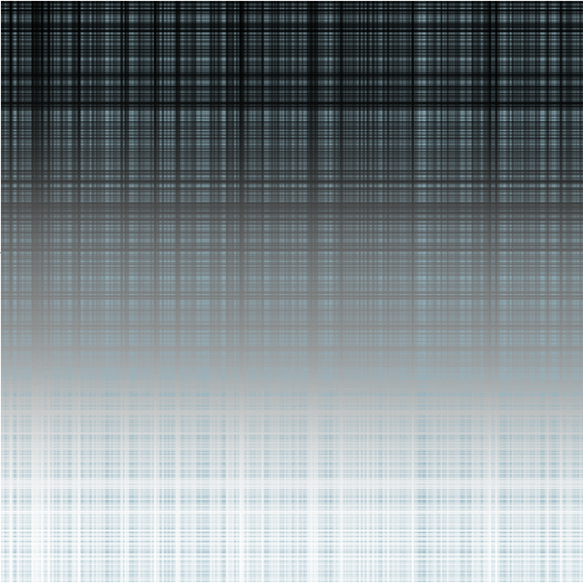
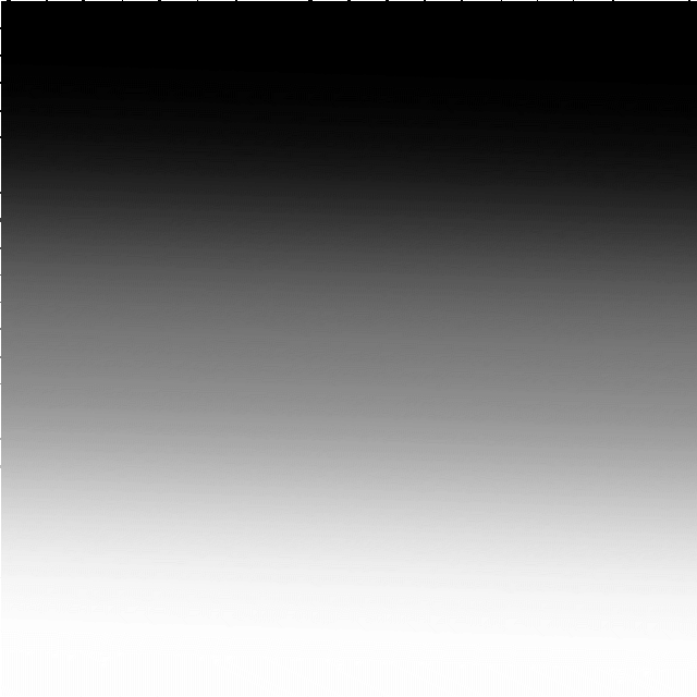
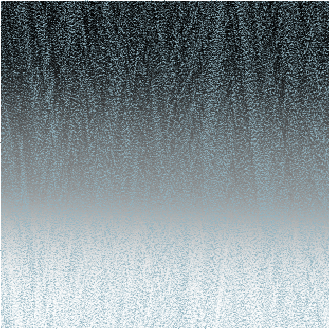
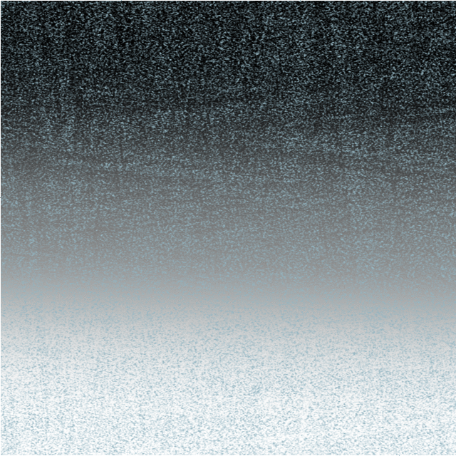
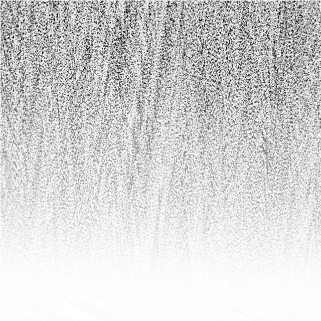
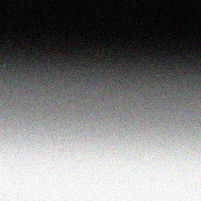
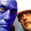
WARNING: for the technically-minded only! The Noise functions in the Filters > Distort> Equations facility are supposed to add (unspecified) noise to an image. The only description I can find of this is in the video by James Ritson. He first duplcates the layer and then uses either noise(x*y)*a or noise4(x*y)*a in his equation. This produces a grain-like effect over his image. The documentation for equations is limited. There is the Expressions for field input in the Help system which gives, under : Noise(seed/x,y), an explanation: Generate 1D noise either from a seed or based on X/Y input with similar definitions for noise2, noise3 and noise4. James uses both the noise and the noise4 functions. In his video he is using the single seed parameter x*y, with the magnitude controlled by the a parameter. I have been experimenting with these noise functions and present here my findings Although the Expressions for field input names the functions Noise ... Noise4, with a capital letter, these will not work. You need to use a lower case n for noise. The function noise2 has no effect. The functions noise, noise3 and noise4 seem to produce identical visible results. The histograms are also identical. Using a single parameter, either a simple number, or an expression such as x*y, has no visible effect unless the Full option is selected in the Extend Mode at the bottom. When using two parameters, they need to be different in the x and y axes to produce any visible result. Multiplying the parameters by a number, such as noise(10x,10y), has no visible effect. I show here the effect of varying these parameters on a simple gradient field: Here is the effect of x=noise(x,y) and y=noise(y,x): The results for noise3 and noise4 are identical, as are noise(3x,3y) etc as are the histograms. If the parameters are the same, say x=noise(x,x) and y=noise(y,y) You get a very different effect: Almost like a tartan effect. If the noise functions are the same in both x and y such as x=noise(x,y) and y=noise(x,y), it works OK, but if you use x=noise(y,x) and y=noise(y,x) there is no visible effect unless you select Full: The difference between using Zero and Full in the Extend Mode at the bottom is subtle. Using Full seems to convert the image into a monochrome effect with the background invisible. However, the noise is based on the luminance of the background. Just for comparison, I append here the effect of the effect of the Add Noise filter (Filter > Noise > Add Noise...): You can control the intensity of the noise here, which is more than you can in any of the noise functions I have described. In conclusion, I would recommend that if you want noise, then use the Filter > Noise > Add Noise... option above until such time as the devs at Serif come up with a more understandable noise function in Equations. Having said that I am not holding my breath on this. Using noise in equations is probably a minority pursuit amongst users and the Add Noise filter is much easier. John
-
Can you guys please port over the distort feature from Serif DrawPlus or PagePlus into Publisher? This has been announced 5 years ago to be on the roadmap for Designer and still is not there. Today, I am using the Distort from PagePlus (=2015) or CorelDraw7 (=1995) to do this and copying the results back into Designer/Publisher. Quite embarrassing.
-
 I'm currently test driving all of the Affinity products in hopes of leaving Adobe's Creative Cloud, but am coming up just a little short on some key tool necessities. The biggest hole I can see is the ability to distort or free transform vector nodes, whole objects or outlined text (curves). This is a tutorial on creating 'curved' text using 'free transform' tools in Illustrator from 2000: http://www.balloontales.com/curved-type/ Or selective scaling when nodes are selected. Here's an example of the function; keep in mind this isn't about WHAT is being created, it's the 'how'. http://www.balloontales.com/tv-shape-balloon/ Just added functionality to node/vector manipulation and I can then say goodbye to Adobe Illustrator. If these functions already exist, can someone point the way to any related tutorials? Thanks! Good stuff so far; just need a few more tools to be GREAT stuff. G.
- 2 replies
-
- 5
-
-
- vector
- free transform
- (and 4 more)
-
 I'm sure its been asked a thousand times but is there any chance of a similar function to Inkscape's path effects being added to 1.7.0 << if it were to happen I would be more than happy to pay for the upgrade from 1.6 A very simple example is shown in this video: https://www.youtube.com/watch?v=aotGj9iJB4U
 -
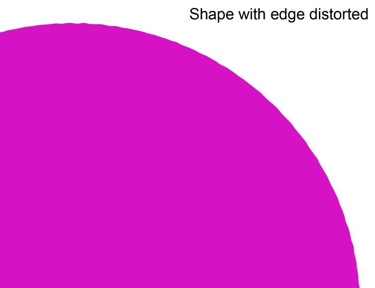
 I'm using Affinity Designer. Besides using a textured stroke or manually adjusting curves/nodes, is there another way to distort the edge of a shape? Pic below is similar to what I'd like to accomplish. I could possibly create a textured stroke to mimic this, but are there other ways or anything automatic? Thanks again!
-
 Oh dear ... seeing the amount of excellent stuff that has been created on the site, I'm almost embarrassed to ask my question. Almost. It's quite simple, really, but it's just about driving me mad. Imagine - Draw a rectangle to simulate a long banner which is going to hang from a wall, with three eylets, top & bottom. Superimpose text. Now, when a real banner is hung, it will distort and droop where it is unsupported - ie. in between the eyelets. The text, of course, will distort with the banner. How do I do that in Designer? I can get the banner background itself to do it (sort of), but how about the text? Can't find anything in the tutorials which would help. I just KNOW I'm going to feel foolish when I'm told, but, at the moment, I'm willing to risk it !! Oh - just in case you haven't already guessed, this is my first outing with Designer.
 -
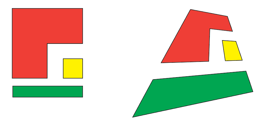
I recently had difficulty in getting the Distort > Equations Filter to work as I thought it should, I was convinced that there was an error and posted a Bug report here. After comment from members @shojtsy and @walt.farrell and moderators @Andy Somerfieldand @Patrick Connor, I finally got it sorted. I thought that an item in the Tutorials might help for others coming to this problem anew. Consider a simple pair of Equations: x=x+y*0.2 y=y*0.7 My original thoughts were that these represented algebraic transformations, that the value of the pixel at position (x,y) would be moved to pixel position (x+y*0.2, y*0.7). Applying this to the image: gives: The bottom right corner of the image is transparent. My expectation was that the height of the text would be reduced to 70%, but it is actually expanded to approximately 140% (1/0.7). I originally expected the slant to be anti-clockwise, but it was clockwise. My original thoughts and expectations were wrong. What actually happens is quite different. For any pixel at position (x,y), Affinity Photo will find the pixel at (x+y*0.2, y*0.7) and use the value of the pixel value there to apply to the pixel at (x,y). Following this logic, the results are consistent with (revised) expectations. John
-
 Hi guys, Is there a DISTORT TOOL or something similar to the distort tool from Fireworks, which allows to distort images? Thanks
 -
 Hi, I'm new here. I bought Designer an hour ago. Do not anyone know where to find distort? Thanks Mak
-
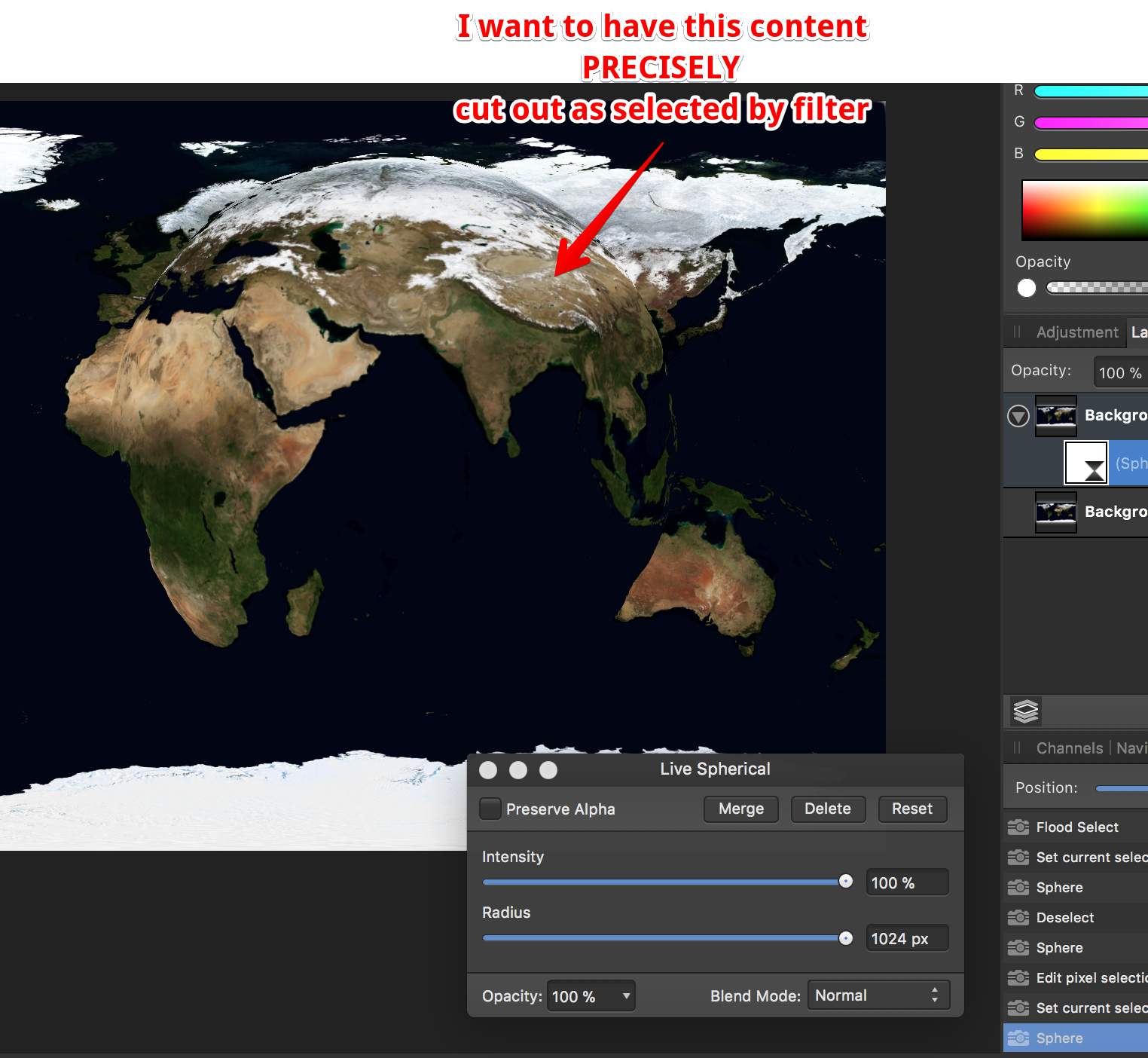
 How do I cut out precisely (!!!) the range I selected with the distortion filter "Sphere" - no matter live or destructive. I tried everything, giving up... FYC: if I make a circle selection first, I never get the range spherized I want to... Why is this filter limited to 1024 pixels??? Thanks for all reply in advance
-
@atfitzy posted a thread about re-shaping a text block. I tried various Equations in Filter> Distort and the best I could come up with is: x=x y+(h-y)*(w-x)*x/w/w/a This produces the required arch in the upper margin of the block. The a parameter allows the user to increase the stretching effect. The default of one has no effect; reducing it will increase the effect. However, I find that reducing the parameter has no effect until the value goes below half, after which it has the desired effect. I can get the desired effect by putting a multiplier at the start of the equation: y+2*(h-y)*(w-x)*x/w/w/a Here are a couple of arched images using this formula: Otherwise the formula works as desired. Before I commit this to a macro can anyone explain this unexpected behaviour in the parameter value? John
-
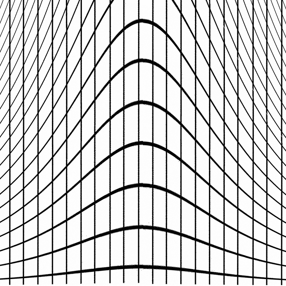
I have been using Filter > Distort > Equations to modify text onto a sine curve. First I rasterize the text, then apply Filter > Distort > Equations with the following formulae: x=x y= y+(h*a/2)*(b*sin(360*x/w/c)+(1-b)*cos(360*x/w/c)) This filter works as intended as a one-off, and whilst recording the macro, but If I then export the macro, and try to apply the macro later nothing happens. The history panel shows that it has been applied, but the image is unchanged. This happens whether I load the macro as a single macro, or if I add it to a library and load it from there. Text onto sine-cosine curve.afmacro Anyone any ideas? John
-
The equations facility in Affinity is not well documented. There is limited support in some AP actions, but the Transform and Distort > Equations filter offers a wide range of functions. This tutorial focuses on using the trigonometrical functions, sine, tangent and arctangent. The argument to many trigonometrical functions is an angle. In mathematics this is usually expressed in radians. However, the Affinity functions expect their argument in degrees. Sines and cosines The argument expected is in degrees, and over 360 degrees, the value of the function varies between -1 and +1. The sine function starts at zero and rises to a maximum at 90 deg, then falls to zero at 180 deg, falling to a minimum of -1 at 270 deg before rising to zero at 360 deg. If we wish to map this cycle to the width of an image, then we can use sin(360*x/w). Typically we would want the amplitude of the cycle (the maximum and minimum) to be more than 1 and -1, so we add a scale factor, measured in pixels. For an amplitude of 100 pixels, we have 100*sin(360*x/w). This gives one cycle across the width of the image. If we want more than one cycle, we can add a multiplier in the argument, so for three cycles per width, we can use 100*sin(3*360*x/w). Note that I use 3*360 rather than 1080 since it preserves the standard 360 multiplier. As an example, here is a checkerboard with Filter > Distort > Equations: x=x y=y+100*sin(2*360*x/w) If we apply this to a real image, we get: This is varying the vertical position of a point along the x-axis. We could vary the vertical position of a point along the y-axis by using the equation: y=y+100*sin(2*360*y/h) For the checkerboard, this would give: And for the Severn Bridge we get: We could even combine them both with the formula: y=y+100*sin(2*360*x/w)*sin(2*360*y/h) to give: or, for a real image: I will be adding further examples using tangents and cotangents.
- 9 replies
-
- 4
-
-
- trig functions
- equations
- (and 1 more)
-
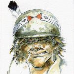
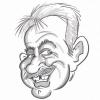
 I would like to distort some portrait images in a kinda weird-ish way. The way I have it in my mind is as if the images were melting, you know like candle wax running down the side of a bottle or like ink which has come into contact with water and the image is partially distorted. Is this possible and if so what is the best way to go about it? ~ Much'O Thanks in advance.
 -
A tool that distorts groups of objects would be extremely useful - the most obvious use would be to distort groups such as squares laid out in a checkerboard or tiled floor design add perspective. Ideally with no restrictions on the directions of distortion - similar to Free Distort. For me this feature is actually essential rather than just useful. Thanks
-
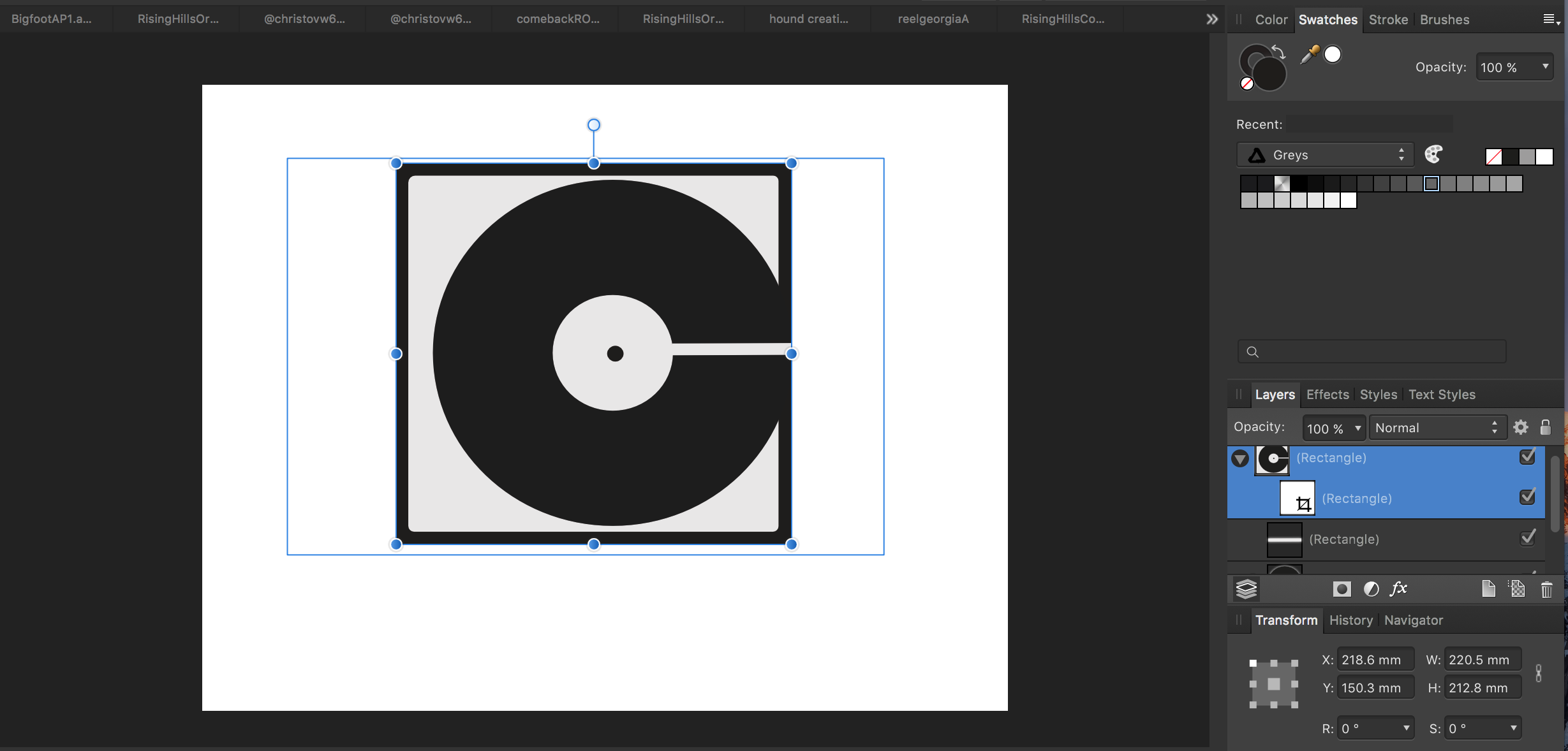
 'morning guys/gals, 2 quick questions please (and thanks): 1) in the image below (thumbnail and file attached) you will see a logo image that was originally on a black rectangular background. I cropped the L and R sides to get rid of portions of the background so as to create an even-ish border. How can I get rid of the still-remaining blue lines outlining the original boundaries of said black rectangle background? ...and, 2) in order to distort/stretch this image (logo portion), don't I simply 'convert to curves' the grouped layers then click/drag whichever node I'd like to 'pull' on? My goal is to be able to manipulate the image by independently move nodes to create perspective changes in some cases, or make the image look curved in other cases (as if on a cylindrical surface such as a telephone pole, etc). Does the image/layers need to first be flattened. Big thanks from a newbie! -Christo CVlogoBlueCropLines.afdesign
-
Recently I face a problem where I had to put a text on to a perspective product in a circular form. I was unable to do that and had to get it done from AI and shift to AD. I also found that there are no text wrap options into this.
-
 As one of the 30+ year users of Fireworks who refuses to use clunky Adobe products because it kills my billing time, I am coming to appreciate the speed and power of Affinity, BUT, for a company that did so much that's thought out so well, the one thing that Fireworks had that I miss would be the freeform distort tool. Effectively you could grab any corner and tweak the box for images or text and stretch or flatten it to any perspective. The best part was that you didn't have to "rasterize" the text and lose the ability to change it for size, type, color, etc. as you were manipulating it. For doing everything from creating quick shadows of something to mimicking the Star Wars disappearing text crawl in a graphic, it worked religiously well and quickly. Speed's name of the game when you compete with others not only on your talent, but billing by the hour, and flipping more jobs in an hour. This would be most handy. Thank you.
 -
 Hi, is there a way to distort an object using an envelope, and/or some kind of perspective tool? I’ve just got to something that would benefit from that, and I can’t find a tool for it. I rather suspect that it’s not there - if it isn’t (and isn’t on the To Do List), can I put in a request for it to be added? Thanks.
 -
 I've been playing with the Distort Filters and I can't see any change at all after applying the Deform filter. Tried every possible combination of adjustments and an A-B comparison of my layers before and after applying shows no difference. What am I missing?
 -
I am sure we could all go on listing “filters I would like to see” and never reach the end. It’s so personal. So I am going to be very simple and suggest a simple modification to an existing one. Cylindrical Distortion is one simple filter I really miss. And there really is no substitute for this in AP. Since this is (I think) simply a one axis spherical distortion could this not be included in the Spherical distort with a simple one axis/two axis checkbox? Far better still would be separate pairs of X and Y sliders for Intensity and Radius enabling any variation of spherical, elliptical or cylindrical. You could have a Lock/Unlock for using the axes separately or together.
-
 Hey guys - I wanted to know how to do perspective in AD so I can keep it vector. Any quick and dirty tricks will be much appreciated. Here's a screenshot of what I'm trying to do. Thanks, Marc