gafvert
-
Posts
64 -
Joined
-
Last visited
Everything posted by gafvert
-
No, but as others have pointed out this issue seems to be pixel misalignment of art board origins. For example it you have an artboard that is sized 1024x1024 it will not result in a slice with that size if it's placed at X: 1000.1px Y: 1000px. Since there is apparently a global pixel grid outside the artboards the export slices are taken from the pixel misalignment will result in a 1025x1024 slice. So that's the first non-apparent thing you need to understand. However, the issue I'm frustrated with is that even when you figure this out and enable force pixel alignment to avoid this issue it seems Designer sometimes introduces some small fractions to artboard origin coordinates when you move artboards. Like making 1000px into 1000.0254px or something. And the problem making this worse is that these fractions aren't shown in the interface, so it still says X: 1000px making you think it's properly aligned, while the hidden fraction values are causing export slice misalignment. To avoid this, you also need to re-enter the values for origins each time you move an artboard. Even if it says 1000px and force pixel alignment is enabled you need to select the field and manually type in 1000 and hit enter to make sure it's actually 1000px.
-
Also super frustrated about this. If I set up an artboard to be 1024x1024 pixels (by manually typing in the values), then make sure they are placed on whole pixel locations (I've learnt this with time) and then create an export slice from this artboard I expect it to be 1024x1024 pixels. Not 1025x1025. Surely it cannot be a feature to not have the export slice for an artboard not be the same size as the artboard size? If I knew this was fixed in v2 I would upgrade just to fix this issue I'm constantly running into. But reading this thread and seeing how long the issue has been around without a fix makes me think it's probably the same in v2? I have a feeling that this problem also gets worse with larger documents, making me think that there's some sort of hidden rounding error going on in the background where the artboard sizes and positions are recalculated from pixels to some other units and then back to pixels for the slices, introducing some hidden decimals we can't see that then cause these export size problems.
-
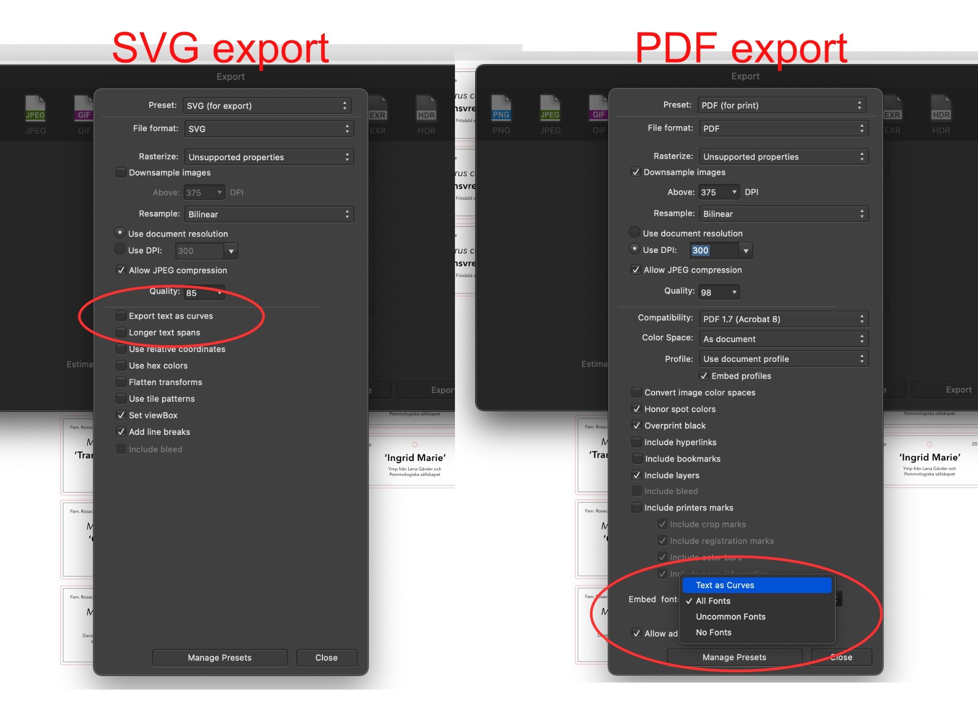
Or just have it be a checkbox like in the SVG export dialogue. Along with the font embedding and other text-related settings in a "Text handling" section that's more or less the same in both cases.

-
Wow, that was quick, and thank you! Yes, this was exactly what I was looking for! However, I didn't understand it would be in the menu for embedding fonts (which in my mind is something else, though related), and since the option is a separate checkbox for svg export I was looking for a separate checkbox with the same name for the same functionality. So I guess the feature request now would be to make this option a little more visible and consistent between SVG and PDF exports instead.
-
Recently when exporting a set of a lot of little signs for lasercutting the producer asked for a file with all text converted to curves. I'm not sure if this is actually needed anymore with embedded fonts in pdfs, but it's still something people ask for for safety. It would be very useful for these situations to have an export setting for pdf and eps to convert all text to curves on export. In I found out there is such a setting, but only for SVG as far as I can tell. So I ended up exporting the file as SVG, then opening it and re-exporting it as pdf to get a pdf file with curves. This feels like a bit of a workaround, and doing multiple conversions always feels like a risk of losing information. So, please add an option to convert all text to curves for pdf export as well.
-
Yep, still very much lacking. Back when I raised this in 2019 I had just migrated away from Adobe Illustrator where I was doing a lot of UX/UI-prototyping, and I was hoping that I could start using Affinity Designer for the same purpose. But largely due to the lack of dynamic object styles I eventually gave up on that and I've stopped trying to do any UX/UI-prototyping in Designer.
- 6 replies
-
- 1
-

-
- styles
- object styles
- (and 1 more)
-
”Rotate view” — required options
gafvert replied to Thomas M. Braun's topic in Feedback for the V1 Affinity Suite of Products
Great, thanks @walt.farrell and @Pšenda. I looked at least three times for these settings in the preferences without finding it. Probably because I looked in the interface, general and miscellaneous sections and didn't find this. Now it works like I want it to! As for the default modifier zoom/rotate functionality it seems weird that on macOS the default Alt + Mouse wheel zooms and Command + Mouse wheel rotates, while on PC Alt + Mouse wheel rotates then? -
”Rotate view” — required options
gafvert replied to Thomas M. Braun's topic in Feedback for the V1 Affinity Suite of Products
I'm looking for a way to disable this feature. In some other application command-mouse scroll wheel is used for zoom, so quite often I use it and end up rotating the entire view a couple of degrees. This is surprising and irritating to me, because I then have to find the rotation reset menu item and get disrupted in my work (because it's very hard to scroll-wheel back to exactly 0° rotation, since it doesn't snap). I could see a (fringe) use case for rotating the view temporarily 90° (which is what I'd expect from View->Rotate Left / Right). But I don't really understand why you'd ever want to rotate the view say 7° (which is what you usually end up with by mistake with the mouse scroll wheel), or 15°, 30° etc. It's a little strange to me to then bind such a seldom used feature the user probably doesn't want to do to such a central input as the mouse wheel. It would make my experience with Affinity a lot smoother if I could disable view rotation with the mouse wheel (or even better have command-mouse wheel zoom like I expect it to). -
No PDF bookmarks
gafvert replied to NorbertWeiss_1's topic in Feedback for Affinity Publisher V1 on Desktop
Any updates on this? Sounds like good news that it might be implemented in 1.9, does anyone know when it will be released or if it now works properly? I'm working on a software manual where it would be very useful if I wouldn't have to use another application to add the pdf-bookmarks after exporting the pdf from Affinity Publisher. -
Improved SVG Exports for Web Design
gafvert replied to Alces's topic in Feedback for Affinity Designer V1 on Desktop
Thank you @VIPStephan for the tip regarding the "flatten transforms" option, that indeed seems to get rid of the extra transform steps. It was not very intuitive to me as I did not expect there to be any transformations to flatten, as I had made no groups of objects and transformed them. However, after a little experimentation, it seems that for Designer every transformation you make of an object results in a group of that object with the applied transformation (even if it's not shown in the application). So if you first draw a 50x50 circle then scale it to 100x100 size you get a different SVG export than if you drew the circle at 100x100 size from the start. Regarding the empty fill rect it seems like it's a residue of when you create your document, I'm guessing it's the original artboard background or something. In the case I pasted in above you can see that I have changed the artboard to be 100x100px, and then selected this preset artboard slice in the export mode to export to svg. So it's extra weird that it's still 800x600. If I instead create a new document setting it to be 100x100 in the new document dialogue I still get the empty rect in the SVG export, but now it's 100x100. Still, with the nice flatten transforms option I now get (with a simple circle instead): <svg width="100%" height="100%" viewBox="0 0 100 100" version="1.1" xmlns="http://www.w3.org/2000/svg" xmlns:xlink="http://www.w3.org/1999/xlink" xml:space="preserve" xmlns:serif="http://www.serif.com/" style="fill-rule:evenodd;clip-rule:evenodd;stroke-linejoin:round;stroke-miterlimit:2;"> <rect id="Artboard1" x="0" y="0" width="100" height="100" style="fill:none;"/> <g id="Artboard11" serif:id="Artboard1"> <circle cx="50" cy="50" r="50"/> </g> </svg> But in my mind as you're exporting just a slice that is the one selected artboard this could/should be just: <svg width="100%" height="100%" viewBox="0 0 100 100" version="1.1" xmlns="http://www.w3.org/2000/svg" xmlns:xlink="http://www.w3.org/1999/xlink" xml:space="preserve" xmlns:serif="http://www.serif.com/"> <circle cx="50" cy="50" r="50"/> </svg> -
Improved SVG Exports for Web Design
gafvert replied to Alces's topic in Feedback for Affinity Designer V1 on Desktop
Came here to add to this. Just tried to generate some simple SVG shapes I'd then use inline in a web project, to keep it clean I set up a file as simple as possible, with just a 100x100 artboard and a simple star in it with no grouping. I expected this to generate SVG code where the artboard size would be the SVG size with just the path of the star in it. Instead I got this: <svg width="100%" height="100%" viewBox="0 0 100 100" version="1.1" xmlns="http://www.w3.org/2000/svg" xmlns:xlink="http://www.w3.org/1999/xlink" xml:space="preserve" xmlns:serif="http://www.serif.com/" style="fill-rule:evenodd;clip-rule:evenodd;stroke-linejoin:round;stroke-miterlimit:2;"> <g id="Artboard1" transform="matrix(0.125,0,0,0.166667,0,0)"> <rect x="0" y="0" width="800" height="600" style="fill:none;"/> <g transform="matrix(9.30233,0,0,6.97674,-65.1163,-48.8372)"> <path d="M50,7L57.329,42.671L93,50L57.329,57.329L50,93L42.671,57.329L7,50L42.671,42.671L50,7Z"/> </g> </g> </svg> As you can see for some reason Designer has added two levels of pointless transformations, first adding a group for the artboard, with a transfrom matrix that makes the raw SVG code inside hard to use. Then a pointless 800x600 rect that I guess is a rest of the fact that the document once started life as a 800x600 template (though there is nothing in the document with that size), finally adding another pointless group around the path with another level of transformation. What I would have liked and expected was something like: <svg width="100%" height="100%" viewBox="0 0 100 100" version="1.1" xmlns="http://www.w3.org/2000/svg" xmlns:xlink="http://www.w3.org/1999/xlink" xml:space="preserve" xmlns:serif="http://www.serif.com/"> <polygon id="Star" fill="#000000" points="50 0 58.5223 41.4777 100 50 58.5223 58.5223 50 100 41.4777 58.5223 0 50 41.4777 41.4777"></polygon> </svg> -
a small feature request [Stroke Selection]
gafvert replied to Tanner4500's topic in Feedback for Affinity Photo V1 on Desktop
I've also requested this, and it's been discussed in the thread Stroke a selection. While creating a shape from a pixel selection and then be able to use that for stroke sounds nice, it also sounds complicated to implement and difficult to get right. What I, and I think @Tanner4500 above would like is just a one step tool to add a stroke to an existing pixel selection, like what's available in other image editors. In other words without changing the selection to selecting an outline and then flood filling it as you need to do now. -
Just wanted to chime in here as well as I found this thread looking for a way to add a stroke outline to a pixel layer selection I had made. This would be very useful to me as well, and one of those basic Photoshop features I had expected to be in Affinity Photo. Like everyone else I realize that Affinity isn't Photoshop, but in this case it seems strange not to offer the basic features to "fill" and "stroke" the current selection, when clearly Affinity already has the technology in place to do it as you can get the outline selection and use the flood fill tool on selections. To me it would seem like a good idea to simply add fill and stroke commands to let the users quickly use this functionality on the current pixel selection in a way they will likely expect it to work, instead of having to figure out (or look on forums like this) how to use multiple tools to get the same result. Converting the selection to curves on the other hand I understand would be much more complicated, and not something I would expect.
-
I'm adding artboards using the artboard tool. Here's what happens if you add an artboard in a newly created document. Like I described above, it removes the initial document area and now you only have the new artboard Creating a second artboard.mov
-
I find this very confusing as well, and was just going to start a thread asking if this was a bug. When we have the concept of artboards, I expect the document to be a an artboard. And that to resize the artboard is to resize the document in a one-artboard document. If I add another artboard I expect to now have two artboards, and a document with multiple pages/artboards that can have different sizes. Currently it seems we have (at least initially) a document that has a size rectangle, but no artboard. This is a little inconsistent, but I guess it might make sense from some legacy point of view that doesn't need/want artboards. However, it becomes very confusing when you add a second artboard. Because this doesn't convert the existing document/pseudo-artboard to an actual arboard, instead it just removes this and now you only have the new second artboard you just created, with all of the initial document being outside. Since this also toggles from no-artboard mode to artboard mode it also changes the background color of the work area which may be confusing if you don't understand what just happened. So ideally I'd wish that all documents had an initial artboard that was the document size. In other words no more no-artboard mode. But at least to avoid confusion it would be nice if adding a second artboard would convert the initial "no-artboard" document rectangle to an arboard instead of removing it. EDIT: When going through all the presents in the new 1.8 "New file" dialogue the "create artboard" setting is enabled like I propose above, but only for the device (like iPad and iPhone) presets, and not for any of the print, web or other presents. I wonder why?
-
Was just looking for this, is there really no such option in 1.8.3 either? I'm working with texture files that are white symbols on transparent background, and it's very hard to see anything with the light tile transparency background.
-
Another two years later, I'd also like to see a blur behind effect! Like Mabel posted it would be very useful for making UI mockups where this kind of frosted glass-type background is now quite common
-
I agree that plugin support for Designer would be interesting, but in my case from a developer perspective. I develop some specialized macOS design software for making halftones and patterns that I think could be interesting to make into plugins to fit in better with designer workflows. And since I'm going away from adobe personally I don't want to build Illustrator plugins, so being able to make plugins for Affinity Designer would be great.
-
Just updated to 1.8.0 and there has been a slight change to the node tool: Now when you have nothing selected and click and drag with the node tool you do get a selection box (which is a good addition!) however, it just seems to work like the Move too selection box and doesn't actually allow you to select nodes (which is a little confusing, why have a selection box for nodes that doesn't select nodes?). Instead it just selects entire shapes so you can then click and drag again to select their nodes (if you've converted them to curves). Still can't seem to select control points or edges of text frames though. So the requests at the top all remain relevant I think.
-
Things still on my wish list for Affinity
gafvert replied to George3's topic in Feedback for Affinity Designer V1 on Desktop
I wasn't aware that it was possible to select these control points with the node tool. It's been something I've been struggling with trying to do, but I haven't found a way to do it. For me when I try to drag up a selection rectangle around them with the node tool nothing is selected (video example: https://forum.affinity.serif.com/index.php?/topic/105832-allow-node-tool-to-select-control-points-of-shapes-and-text-fields/ )? But maybe that's a bug, or is there some modifier key or something I need to be pressing to also select these types of control points? -
Hello, thank you for your replies, but I think you misunderstand what I'm asking for. I know the Affinity control points are not simple bezier spline nodes, and there may be time when this is beneficial. I also understand that since it's such a fundamental part of their design that's unlikely to change. What I'm asking for is to be able to select and edit these "special" control points as well using the node tool, just like you can edit curve points. As you currently cannot (see illustration) the only way to do this is to convert the shapes, which is frustrating/confusing and what I would like to avoid. For text frames I haven't found any way to do it as the "convert to curves" for a text frame converts the text to outlines, and not the text frame. As for the "Isolation mode" of having to first select a shape before being able to select the nodes in it I agree that this if useful sometimes like you say. However, the current behavior could be retained when you have something selected with no change and still add what I was asking for: letting the user draw up a selection rectangle that can select nodes in any shape when you don't have anything selected. Currently trying to click and drag with the node tool if you have nothing selected does nothing at all. NodeSelectionIllustration.mov
-
I agree that this is hard to understand and frustrating (see below for similar/related request). Apparently the this is due to Affinity having curve shapes (what you usually think of as vector graphics shapes) with nodes you can select with the node tool. However, most basic shapes like boxes and squares and text fields aren't such curves with nodes when you create them. Instead they have some sort of "control points"/handles that look like nodes for the corners, but aren't. So you have to convert the shape to curves first before you can use the node tool. Why the node tool doesn't allow you to edit these control points as well I don't know.
-
Things still on my wish list for Affinity
gafvert replied to George3's topic in Feedback for Affinity Designer V1 on Desktop
Nice tip with the optional mode for drawing up the selection area for the node tool, didn't know about that. Still wish it would let me select controls points for basic shapes and text boxes though. Anyone know if this is added in 1.8? -
Stroke width changes when pasting in group
gafvert replied to garrettm30's topic in V1 Bugs found on macOS
Yeah, at the core it feels like this is a more generic issue with converting between different units and DPI resolutions (between different documents or when changing the resolution), where different properties scale inconsistently (for example the stroke, corner rounding and size of a shape may scale differently). The stroke width case was the first I encountered, and that was quite easy to get around with the "scale with object" setting for stroke. However, I also encountered the problem with absolute size corner rounds, and also drop shadow radius and offset being scaled incorrectly when set to pixel values in one document and then pasted into another document with a different DPI setting. And there the only way I found to get around the problem was to set both documents to the same DPI setting (and sue the same units for safety), which unfortunately also meant I had change the rounds and shadows as they changed when I changed the DPI. Hope this is fixed in v1.8. And I hope we get to use it soon! -
Wow, that's such a relief, I didn't know about this setting. Instead I found myself holding down space from time to time as this apparently also hides the text box frames while you hold it. Perhaps that setting could be renamed "Show text box frames" or something similar that would make it easier to find and understand what it actually does. A setting to convert between artistic text and text boxes would still be very useful though.