

HairyDalek
-
Posts
67 -
Joined
-
Last visited
Posts posted by HairyDalek
-
-
One option that occurred to me today is to use Symbols. Try this:
1 - Create a line in Affinity Designer. Assign a stroke
2 - Select the line and make it a Symbol in the Symbols palette
3 - Drag a new instance onto the page
4 - Switch off Synchronising, and change the colour and width of the line. Switch synchronising back on (important)
5 - Drag one symbol over the other

6 - Now, using the line editing tool, you can change the shape of one of the paths and BOTH will change.
7 - You can add points t one path, and the other will inherit them.
This does not address the real issue, bit it’s another method that may work for people here.
-
It started working for me, but only when I dragged ANOTHER new instance of the Key symbol and started working with that. Note - the previous instance of the Key symbol was added to the document in the same session. Are these getting detached accidentally?
-
Sadly, this is not the case for me. I’ve even go as far as putting NEW instances of a symbol in my file so that when I modify the, all the instances of the symbols will be updated.
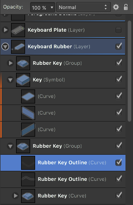
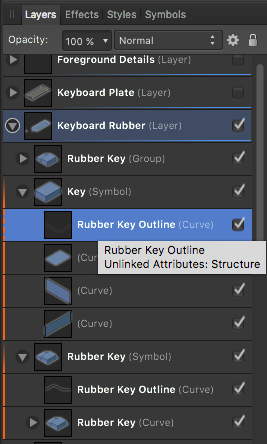
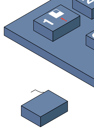
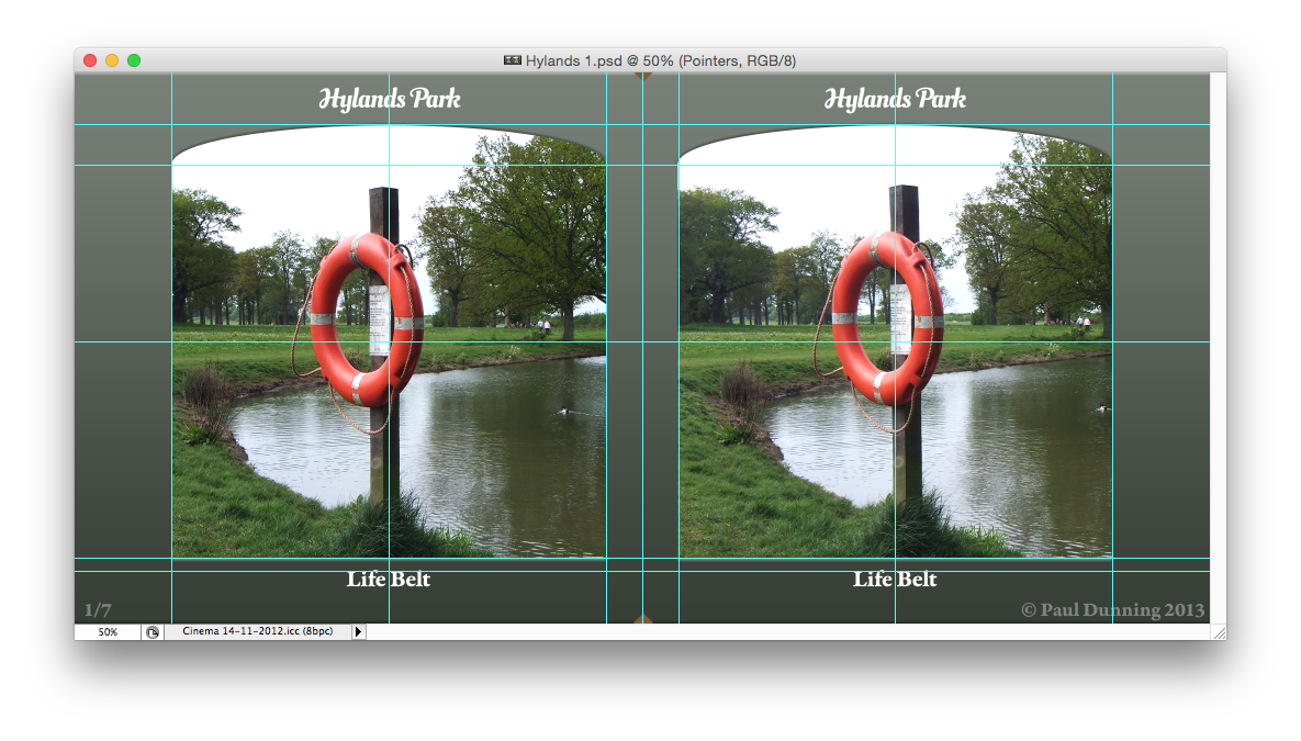
1 - Screen shot 1 shows an item from a group called Rubber Key and a symbol called key.
2 - Screen Shot 2 shows what happens AFTER I have dragged an item called Rubber Key Outline into the Key symbol. It has no orange line down the side, nor do any of the instances of that symbol update.
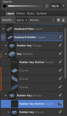
3 - Screen Shot 3 shows what happens if I drag a line from another Symbol to the symbol I want to change. I get a dotted orange line.4 - Screen shot 4 shows the result of the above operation in line 3 - The instance of Key that I dragged the line into is update. However, I am expecting the key with the 1 on it (yes, it’s a Spectrum keyboard before anyone asks) to get that change too. It doesn’t. None of the instances of the Key symbol do. The symbol is Attached and Sync is on in the Symbols palette.
-
HI,
I’d like to know how I can add an object to an existing symbol. I have a few instances of a symbol in an i,mage, and I want to add some extra detail. How can I do this? If I draw an object inside a symbol’s container, all the symbols in the image are not updated. How can I make it so that they are? Thanks.
-
In Affinity Photo (I expect this is the same for Designer), the Export Persona has a number of options for sizes in for the slices. For example, I can choose 1x or 2x, 100w, and other sizes. Nowhere can I say “export to a width of my choosing”. So I can’t scale an image to, say, 900px this way.
If I go to File>Export, I can. However, as the Export persona seems to retain that data, AND I could technically get it to export more than one size per slice, I’d like to see custom dimensions in the export options in the Export Persona too, please.
-
Can we have Macros in Affinity Designer like you have in Photo, please? I’ve been working on an illustration which, had Macros been around, would have saved me a _lot_ of time. As it is, I’ve had to repeat the same three or four transformations many, many, many times and different objects.
-
-
Blimey. I was going to post the self-same question. What luck I found it on the first page of the forum!
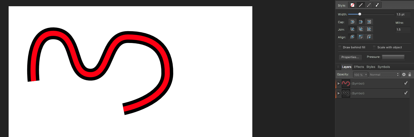
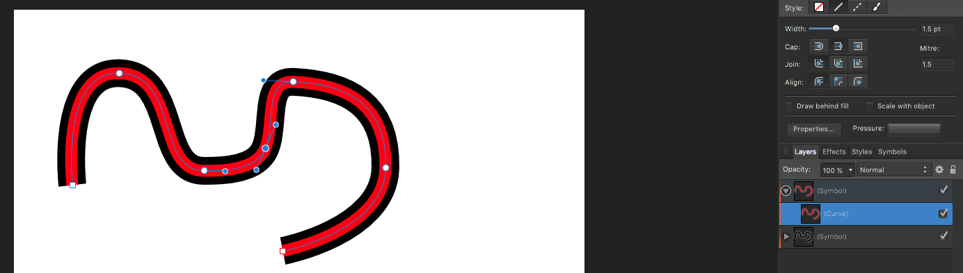
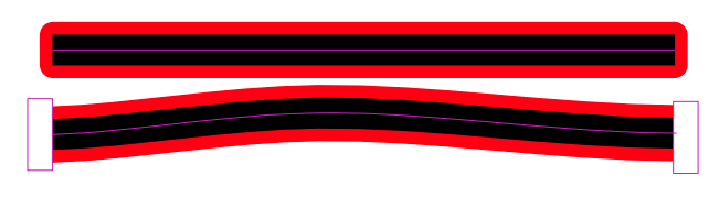
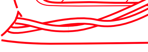
My problem is related, but not to do with maps. I’m re-working some car maintenance diagrams, and as you’d expect there’s plumbing and wiring involved. I’ve found that trying to “eyeball” parallel lines is impossible, so I’ve tried the Outline FX option. That works up to a point. As the wiring/pipes tend to twist around, and the diagrams reflect that, this option isn’t really helpful as I have to cut the line in places so I can change their layer order. When you to this, the end caps appear which is not desirable. What I want is to only have the line outlined along the direction of travel. See the black/red image example. The caps should be clipped to the ends of the line.
What I have been doing is using two lines - one ontop of the other - with the one the colour of the “fill” being thinner than the one the colour of the outline. That way, I can do the “twisting” thing, BUT you’ll see little artefacts appear where the line segments join. I expect I can remedy this with the use of rounded and caps in places, but it’s a real faff, especially if you need to make an edit later on - both lines need to follow each other perfectly.
I’ve looked at the examples here, but none of them leap out at me as *the* solution to use in my situation. Some of these diagrams are really complex, with pipes and wires going in various directions, and the layering of elements has to be pretty precise to help the image make sense.
Hoping that Affinity designer will get more options to help this kind of thing in the future.
-
Seconded again (thrived, fourthed...?). I wrote Actions for (the late, lamented) Freeway - these were mostly JavaScript, but you could patch through to AppleScript and any app or command line tool to enhance Freeway’s output. Being able to script these apps using something like JavaScript or Python would be a great addition to the Affinity mix.
-
Like this feature a lot - been waiting for something that makes this kind of editing easy for a long time, however there’s a thing I’d like to see added to this.
First off, it seems that enabling the projection viewing for a 360 degree image is limited to the background layer. This is OK, but your teaser video touches on this a little without mentioning too much. If I create a layer over the projection (your video shows a poster being added to a picture frame), then that layer is not part of the projection UNLESS it’s merged down. That means that any elements that are included as part of this are, inherently, uneditable in the future.
I’d like to be able to group elements together, and have that group be subject to the projection, not just one layer. So text, added elements, images, etc. are all accessible in the future for editing.
-
Hi,
Been giving the Panorama stitching feature a go, but I’m not sure it’s working properly for me. I’ll tell you why. I’m using a Sony NEX 16mm lens with the fish eye adapter, which gives you a focal length of 10mm. Using apps like PTGUI, I can get a prefect stitch by manually entering in the lens’ parameters. However, with Affinity Photo, I can’t get anything near a decent stitch because I can’t override the lens information. The fish eye lens adapter does not get logged in the image’s EXIF data, so I assume that Photo is taking the recorded lens’ focal length and applying that.
What can I do to ensure that the correct lens data is being used? Is there and override in Photo that I’m not seeing?
Thanks.
-
Hi,
just been trying the same thing and after failing, I did a Google on the subject and this was one of the results. So, chalk up a “me too” on this!
-
This week, I learned that Softpress, who made the web design application Freeway, closed its doors for good. Not a great start for the week for anyone involved in that project with present and past. I’ve been using and had input into the Freeway project for the best part of twenty years.
For those who don’t know, Freeway is a DTP-like web design tool. You draw items on a blank page, and Freeway builds the HTML/CSS necessary to display your design in a browser. Extra functionality can be added using Actions - plugins which run at publish time to amend output. Actions can do a multitude of things, from massaging the HTML, to repurposing it for PHP (or indeed other server side scripting languages), and run using a JavaScript engine.
The recent video posted of the Affinity DTP project, which showed responsive behaviour for print really chimed in my mind. If, I thought, they are doing this, then they’ve clearly solved UI problems that Softpress were’t able to with their responsive offering. The idea that this application could be tuned not just to printed documents, but also HTML/CSS/ etc. got me thinking that here’s a potential for a Freeway replacement.
And, rather nicely, it would be borne from a DTP application - just like Freeway was all those years ago.
So, my request - and I know it’s big ask, but I really hope that the minds at Serif can be turned to this - is a DTP-style web design tool in the Affinity brand. The Affinity software I have already feel more than familiar to me, and being able to build websites in an environment that feels familiar like that would be fantastic. DTP for print is just part of the tool kit for a modern designer - web sites really should be there too.
-
Hi,
is there a way to distort an object using an envelope, and/or some kind of perspective tool? I’ve just got to something that would benefit from that, and I can’t find a tool for it.
I rather suspect that it’s not there - if it isn’t (and isn’t on the To Do List), can I put in a request for it to be added? Thanks.
-
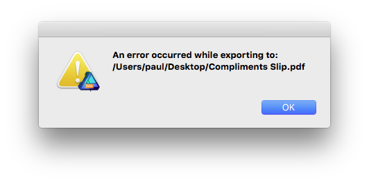
Interesting - if I convert all the text elements to curves, the problem goes away, and the file is exported.
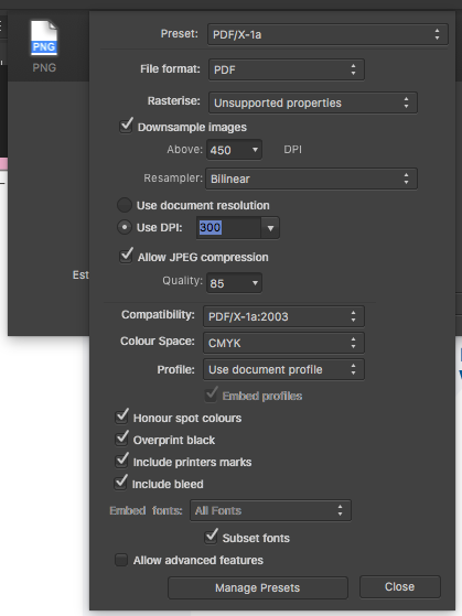
In PDF/X-1a, the Embed fonts option is greyed out (the greying out looks rather messy, BTW):
so I can’t opt to have text converted to paths.
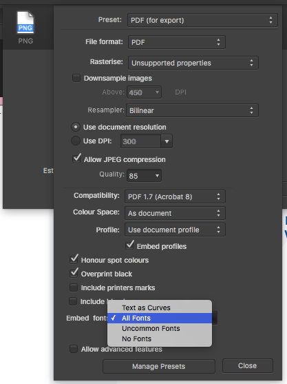
While in other PDF export options, that dropdown is enabled, so fonts can be converted to paths:
-
Hi,
the PDF/X-1a error still happens with this beta as well.
Here is a .afdesign file that I have a problem with.
-
The PDF X-1a preset is still throwing errors when I use it. A pain as I’d to be use it soon (yeah, I know, Beta Software).
-
Hi,
Looking at MOO’s help pages, they recommend outputting to the PDF/X-1a:2001 standard. However, that’s not listed in Affinity Designer’s output options fro PDF.
Moo’s page has a question about pre-flighting PDFs for their service here:
https://support.moo.com/hc/en-gb/sections/200586084
VistaPrint doesn’t seem to specify a version of PDF, but they do seem keen on you using Adobe Acrobat Distiller in some of their help pages.
Anyway, what}s the best way to use Affinity Designer (and Photo) to create PDF documents that meet the various specifications by services such as Moo?
-
I'm sure this has been asked for before, but I'll ask it again :-)
Is it possible to create a series of automated steps that will let us do repetitive changes in one hit? I am specifically thinking of isometric illustrations, where you draw the top and sides flat, and apply a series of transforms in a sequence to convert them to an isometric version.
For example:
Scale vertically by 86%
Skew by 30 degrees
Rotate by 30 degrees
I made something for iDraw that can do this (one button click does all you need), but I'd like to see similar in Designer.
The Isometric grids are good, but this functionality is really handy if you have something complex.
-
I have a number of Photoshop files that have Smart Objects embedded in them. Affinity Photo does not load them as Embedded Documents, but appears to raster them as pixel layers. Obviously, I want them to be Embedded documents.
I have a file that I am sending to demonstrate another problem I have reported which also shows this problem.
-
It would be great if you could post the file here or send it to support@seriflabs.com
I’ll email you a link to it when it’s uploaded to DropBox. There’s another problem it highlights too, which I am about to report.
-
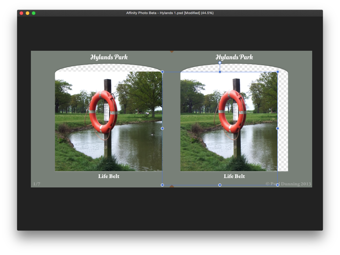
I have some Photoshop files with Embedded Documents (Adobe calls them “Smart Objects”) which are masked. In Affinity Photo, the mask seems to have slipped. See screen shots of how they appear in PhotoShop and Affinity Photo.
Affinity Photo:
Photoshop:
-
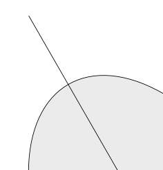
Here’s one - possibly related to my previous question about construction lines.
I have a distorted circle and a line - the line is at 30 degrees (I’m looking at how to do Isometric drawings), and I am wondering how to snap a point to the place where the circle and the line intersect (see attached thumbnail). This will help with building cylindrical and curved shapes in isometric projection.
There is (theoretically) a way to achieve what I want, but so far, not been able to do this in AD (I’ll write a step-by step for that problem when I have the time to do all the screen grabs I need).
So, for now, this is a simpler way to achieve the same kind of effect.
-
Construction Lines are mentioned in the Snapping Options, but greyed out. How do I create these? What do they actually do? I can’t find any mention of them in Help.


How to create double contours in AD?
in Pre-V2 Archive of Affinity on Desktop Questions (macOS and Windows)
Posted
So, using a couple of symbols for roads, here’s a simple map. There are three lines for each road - they provide the outline, the road colour, and dotted line down the middle.
Here’s an Affinity Designer for others to have a play. Map.afdesign