Jeroen
-
Posts
67 -
Joined
-
Last visited
Everything posted by Jeroen
-
Sorry, cannot duplicate to 1.6. Option to load channel to mask is not available, and I do not know of any other way.
-
Thanks for passing this to the dev team, and for coming back to me. For clarity, I was not saying it is a bug. I was asking how it worked. And still am curious. Maybe once I know, I can use it to my advantage. And I would like to understand what the program is doing for me anyway. See my more detailed question in my posting. But now you that mention it, I wish it were different. I wonder if there is a reason to have it this way? It seems so logical that inverting a selection would also "invert" the mask. And I cannot think of a compelling reason to do it like this. I would like to know what I am missing here, if anything. Also, I am wondering if there is another way to achieve what I was trying? Seems like a natural thing to wish for. Again, I would like to understand where I may be wrong. Thanks, Jeroen.
-
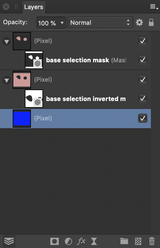
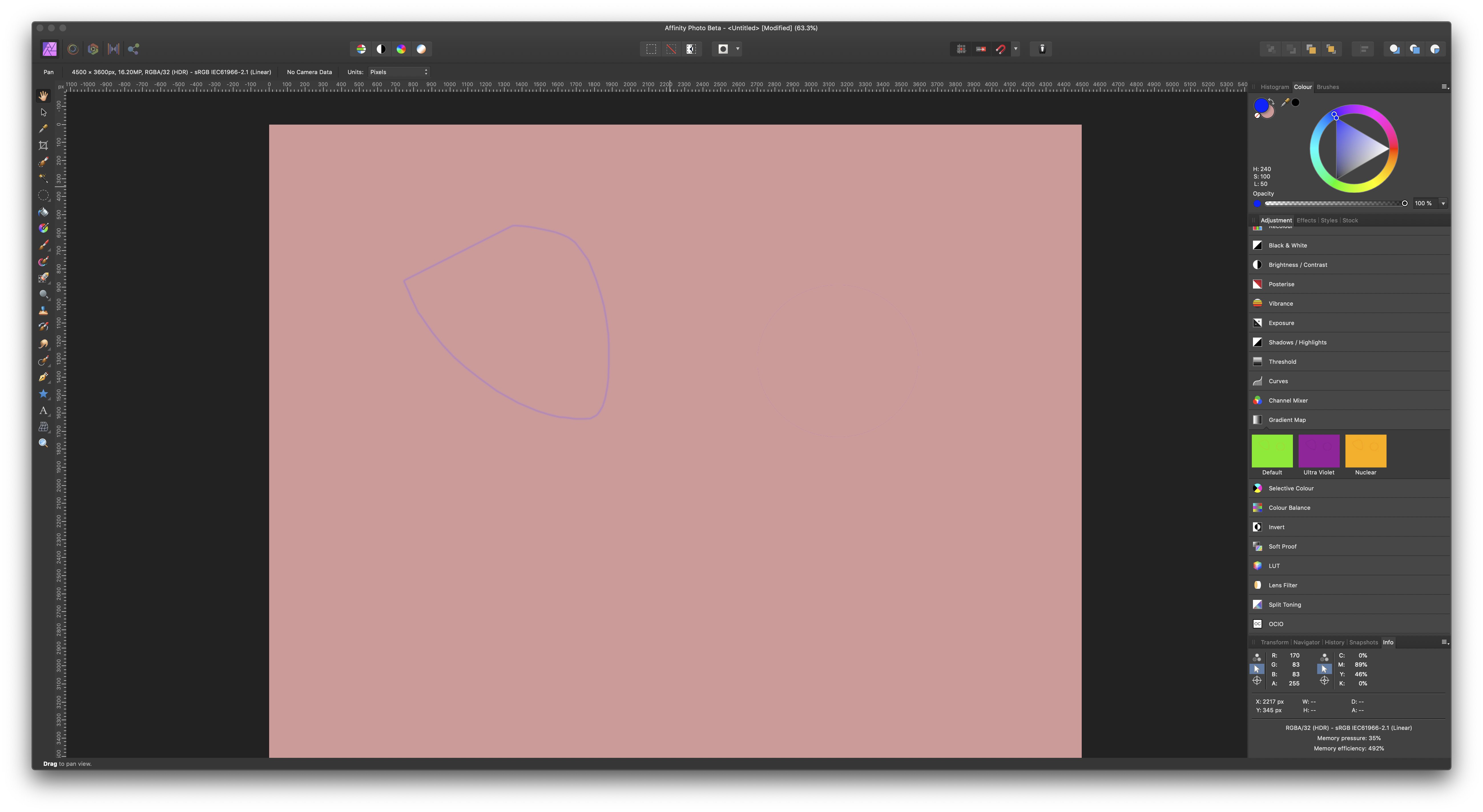
I am trying to understand what is going on under the hood when I invert a selection. Situation: I have an image with a selection. The selection consists of two parts, one (at the left hand side) done with the freehand selection tool, the other (to the right) with the elliptical marquee tool. The freehand part has a blurry boundary, the elliptical part has a sharp boundary. I now want to create two layer masks, one from the selection and the other from whatever is outside of it. I use Invert Selection for that. The idea is to stack two layers with the original image, with one of the masks applied to each of them. Hopefully, each mask will let through just enough so that together they will blend into the original image. I expect normal blending mode should do the trick. My way of working is the following: - the original selection I save into a channel that I call "base selection". - I then invert the selection, and save the result in a channel called "base selection inverted". - I create a pixel layer and fill it with pink colour. - I duplicate that layer. - For each of the two layers I create a mask. The "base selection" channel I load into alpha of the first mask, the "base selection inverted" channel into alpha of the second mask. - I stack the two layers with normal blending mode. - I activate both layers and their masks. - Finally, to see clearly what is happening I create an extra blue pixel layer that I use as background. This is the resulting layer panel: I would now expect, perhaps naively, that I would see the original pink image back, since the masks are complementary and both let their own part of the original through. Instead, I see the following: Whereas the elliptical selection to the right is invisible, the blurry freehand selection to the left lets part of the blue background shine through. I now have the following questions: - how exactly is the selection converted into a mask through the channel? As I understand it, a mask is a mapping that tells what opacity to assign to each pixel of the (pixel) layer it is assigned to. White has 100% opacity, black is fully transparant. Fine. For black and white positions in the mask, this works. But if there is a position in the mask with "grey tonal value", an opacity between 0 and 1 is assigned. What is the formula for that? How is this "gray tonal value" determined, and once you have it, how does it translate to an opacity number? - How do the opacity numbers relate between a mask derived from a selection, and a mask derived from its inverse? Are they complementary, i.e., add up to 1 in every case? - From what I am seeing, it looks like inverting a selection does not necessarily lead to masks that are complementary in the sense that they can work together to restore a full image. They may leave spots with less than full opacity, if selections have blurry edges. This leads to the following question: is there a way to achieve what I am aiming for? Or am I missing the obvious here? Thanks to everyone who read through all this. I do hope you can shed some light. For reference, I attach the project (done with AP 1.7.0.128). Jeroen. selection inversion test.afphoto

-
Of course! Thanks.
-
Only now saw this reply... thank you for taking notice. I just made a reply to >|<, and you might refer to that. Following is a brief excerpt. In that post, I take the position that (a) a gentle renaming would help, (b) an information panel would be excellent, and (c) clamping should perhaps better be made optional, rather than doing it automatically. Coming to think of it, (b) in itself might obviate the need for (a). Speaking for myself, being primarily a landscape photographer, I am not normally into special effects, but when I experimented with 32 bit overlay blending I achieved some spectacular effects which I liked a lot. I would not block that road forever. Another issue is that clamping destroys a lot of information. The reason for 32 bit is just to have that information available when and where you want it. Pity to lose it. One idea might be to optionally "unclamp" after your operation, let's say blending. All pixels that are outside the visible range after blending would then revert to their original value, at least if that also was out of bounds. The ramifications of that can be difficult to grasp intuitively, but in my view, so are many mathematical operations anyway. I can think of variations on this theme. Thanks again, and congratulations with all the fine work you are doing.
-
I now agree. With help of your tip on viewing floating point values I gained a better understanding of 32 bit unbounded editing, and this is indeed how it should be done. Understood. So, the value range in 32 bit is unbounded and the software displays from that range whatever lies between 0.0 and 1.0. The rest is visually mapped either to black (0,0,0) or to white (255,255,255). But internally everything retains its proper value, so that when you shift the values, as you can do in the preview panel, they come to life again if they then fall in the displayable range. I hope I get this right now. Also, "invisible" values still influence all kinds of mathematical operations, such as layer blending. This can make for surprising, but very interesting effects. So, 32 bit editing is actually a very different beast from 16 bit editing (which, by the way, according to James Ritson (https://www.youtube.com/watch?v=UOM_MmM4rvk, 0:22) is based on integer representation of values, not floating point. Perhaps intermediate calculations are done in floating point to avoid cascading of rounding errors, I don't know). Naively, one might think that 32 bit is about better precision, which might be useful in some cases. But much more importantly, other than 16 bit it keeps lots of information that is invisible but still, in principle, could influence operations you perform on what is visible. Weird but interesting. Having said that, I still find it very misleading that Serif has chosen the same name for operations in 16 bit or 32 bit, respectively, that actually are very different in their visual outcome. I can see that one can take the position "the formulas are equal, therefore we call it the same". But is it unreasonable that a user, seeing the same name of the operation in 16 bit and 32 bit UI's, virtually indistinguishable, expects the results of applying it also to be close to one another? Especially where this operation has a generally (also outside of AP) recognised purpose, namely, to achieve a certain visual effect (a contrast enhancement in the case of overlay blending). I would not want to argue that for example, overlay blending should clamp the values beforehand in every situation. Keeping them free can create very interesting effects, and why forbid those? But (a) it can confuse the user who might expect an effect he is familiar with and (b) it forces a work around such as your extra white layer if the user wants to achieve that effect in the first place. if I could make a suggestion, it would be along the lines: - Amend the name of the 32 bit operation to, for example, "(un)bounded overlay" instead of just "overlay". This communicates a gentle warning to the user. An optional information panel to explain the situation might also be nice. - Create a setting on the operation to choose for "clamp to visible", as per your suggestion. There could be a global default setting, but it should in any case be settable per individual operation. An extra white clamping layer would then not be necessary. Clamping may have undersirable side effects. The invisible information is gone forever. (Actually, not necessarily. In theory, after calculation of the new visible range using the clamped values, the invisibles could be "unclamped" again. That could have interesting but difficult to grasp ramifications, I think.) There could be ways to deal better with it. One of the things I wished there were in 32 bit, when I was experimenting, is a filter to apply a value shift to a layer. At the moment, I can use preview to see the effect of value shift, and thus change what is displayed, but that seems only to impact the visual and not to have a lasting effect. I would like to be able to apply it as a filter in the layer stack. Thinking further, there could even be a curve to map values to values. Whatever comes out between 0.0 and 1.0, will be displayed with that value. Outside of that, it will be displayed either black or white. Then your white "clamp" layer could be replace by a "clamp to visible" filter. Looks interesting to me, but needs further thought. BTW, you do not know of such a value shift filter, do you? I could not find it. Thanks for listening to theses ramblings, and I would be interested in your views.
-
Thanks, that clarifies a lot. I did not realise the answer was in your file all the time. Clever to use a regular white filled mask with Darken blend mode to clamp to regular white. And it confirms that, indeed, 1.6.7 has exactly the same problem in 32 bit development. But I think you apply the formula too hastily. The formula expects all values to lie between 0 and 1 to start with. From the same Wikipedia page: "In the formulas shown on this page, values go from 0.0 (black) to 1.0 (white)". This means that all values should first be normalised to lie between 0.0 and 1.0, before the formula may be applied. A value like 1.73 should not be used. No negative values can then ever be generated, and, in fact, white remains white: f(1.0, 1.0) = 1.0 - 2(1.0-1.0)(.01-1.0) = 1.0. Now, I have no idea how Serif maps the internal 32 bit floating point pixel representations to normalised values between 0.0 and 1.0. Nor do I know how the demosaicing algorithm assigns those floating point values to pixels in the first place. I assume all raw development programs have their own way of doing that, with slightly different results. A trade secret, if you will, and very camera dependent. I am doing some experimentation to get some grip on what is really going on behind the screens. For that I need some kind of idea what the floating point representation of a pixel is. You might help me with that: Where do you see that my white has RGB value 1.73,1.73,1.73? That must be related to its floating point value. In the Info panel I see only the regular 8 bit RGB values, which are 255,255,255. And those values do not change after application of the fill layer. So that tells me nothing. But this must be too coarse a way of looking at it, since the floating point representations must be different or your approach would not work. So, where do you find that my white RGB pixels are considered 1.73,1.73,1.73 over-white, instead of 1.0,1.0,1.0 regular white? Thanks for you help.
-
For the record: Problem still present with AP 1.7 beta 1.7.0.125 on MacOS Mojave 10.14.4.
-
Are you sure about 1.6.7? I don't see it with my file on 1.6.7, 32 bits (MacOS). All concerned pixels are white, as they should be. Before I log a bug with 1.6, based on your statement, could you provide an image where you see the problem with 1.6.7?
-
My apologies if I angered you. I myself felt annoyed that you seemed to keep denying my position that there is a real problem in the software, without addressing my arguments. This might have coloured my replies in turn. Sorry again if that angered you. Perhaps it was all miscommunication. To be clear, my posting was not so much to ask for a way around the practical problem how to deal with a faulty implementation, but to alert Serif to a possible issue with their beta software. After all, that’s what beta’s are for. That I now, thanks to you, know that the same issue exists with 1.6 makes it all the more relevant. You suggested a practical way for me around the problem for now, and thank you for that. For myself, the simplest solution is to stick to 16 bits until the problem is solved. I can live without 32 bits. Thanks again, and no hard feelings I hope.
-
A workaround to me is not a solution. There is, I think, nothing I can further say that might convince you. So unless something new comes up, I will close this discussion, file the bug, and move on. Thank you for your particiiation.
-
Let's hope it's that simple. Anyway, I will log it and we'll see what happens.
-
Sorry >|<, but Casterle is right. You keep saying that the behaviour is a consequence of the way the function is implemented. I get that. But the point is, that this implementation does not result in a proper overlay blending as is generally defined (and as is realized in the 16 bit implementation). The only conclusion from this, is that the 32 bit implementation is faulty. There is no other way of looking at it. To be very specific: if you look at the formula I quoted, you find that if you overlay-blend an image with itself, all white pixels come out white again. In my 32 bit example, they come out black. That is wrong, period. Since you tell me that this also occurs in 1.6 with 32 bit, and thank you for that, apparently this is a bug in 1.6 as well. I will log it as such in the proper forum.
-
You are right, my formulation was imprecise. And you are correct in your response. But I stay by my opinion: overlay blending is done incorrectly in 32 bit photo persona. Let me try again. Suppose I have a raw file and develop it twice: once to a 16 bit image, and also to a 32 bit image, These images will be very close in appearance. From you, I understand that in the 32 bit photo persona, the values are internally represented as floating points, not 32 bit integers. Fine. With 16 bit, they are certainly integers. Now suppose I perform the same user action on both, similar, images. In my case, applying overlay blending. This rests on a well defined mathematical formula, which is independent from precision or from integer vs. float considerations. I therefore expect that the results will look similar as well. But that is apparently not the case. Which is what I consider a bug. As argued below, the 32 bit implementation simply does not achieve its goal: overlay blending. It is in error. By extension, I would like to formulate the following design principle: in all cases the user should be aware that choosing between 16 bit or 32 bit in the Develop Assistant might impact precision in the final image. But s/he should also be confident that other than that any operations on the image will have similar results. This is an opinion, but a very reasonable one in my view. I would be interested to hear arguments to the contrary. In any case, the current implementation violates this design principle. === The following elaborates my statement that "algorithms used in 32 bits should be a close approximation to those used in 16 bits, only more precise". Which does not really identifies the problem, as you point out. But that does not mean that all is well. Let me summarise conceptually the steps taken during editing with overlay blending, as I understand them. - in 16 bits blending this translates into a transformation from an array of 16 bits integer values to another array of 16 bit integer values. These arrays in turn are rendered on a screen or on paper. This will normally go via an intermediate step where an 8 bit RGB array is generated. - in 32 bits it is different. Values are represented as floating point, not as integers. Very well. It gives much more precision, especially with many operations in a chain. At the point of rendering, there will be a conversion to an integer array. Whether these are internally 32 bit or 16 bit I don't know, but that is immaterial to the discussion. In either case, in the end 8 bit RGB is again generated for display or printing. For precision, calculations take place as long as possible in the floating point realm. Now to the problem at hand. It is the task of the implementation to realise overlay blend mode. There is a mathematical formula for that. Taken from Wikipedia (https://en.wikipedia.org/wiki/Blend_modes#Overlay): f(a, b) = 2ab if a < 0.5 f(a, b) = 1 - 2(1-a)(1-b) otherwise where a is the base layer value, b the top layer value. These formulae are independent of representation as integer or floating point values, or of bit size. Any real implementation will be an approximation. A good implementation makes the approximation mathematically as close as possible given the circumstances. If, therefore, the 32 bit implementation of overlay blending gives very different results from the 16 bit implementation, one of the two must be at fault. And it is obvious in this case that it is the 32 bit implementation. Technically, the problem appears at the point where conversion to integer takes place. Either that conversion must take into account what floating point has done to values that is significantly different from what integer does, or the implementation of floating point overlay transformation must be adapted to the integer conversion algorithm. Or both. Bottom line: Overlay blending is done wrong in 32 bit photo persona. This is not necessarily due to either the way floating points calculations are done for overlay blending, or to the way floating point is converted to integer, but to the interplay of the two.
-
I understand this explanation in the sense that the mathematical formulae for overlay blending mode, when applied to floating point values, can yield negative values that then become zeros when converted to integer values, thus leading to black pixels. In that sense, all is well. Mathematically, that is. But I find it surprising, to say the least, that the apparent behaviour of an action like applying a layer blending mode could be radically different depending on whether I work in 16 bits or in 32 bits. Of course there would be differences, but I would expect those to be related to precision (banding, etc.). Not to white pixels to suddenly becoming black. Mathematically speaking, the algorithms used in 32 bits should be a close approximation to those used in 16 bits, only more precise. And the conversion from floating point to integer should also be as perceptually faithful as possible. So, regardless of the explanation how it happens, unless someone convinces me otherwise, I consider this a bug.
-
Ahh, thanks for that.
-
Attached beta project has one pixel layer with overexposed areas. These show as white. If I duplicate the layer and set overlay blend mode, the overexposed areas are shown as black. The info panel shows them as 0,0,0,0. Upon export to jpg, these areas remain black. Same does not happen with 1.6. overexposed.afphoto
-
Layer mask issue - suspected bug
Jeroen replied to Jeroen's topic in [ARCHIVE] Photo beta on macOS threads
Neither can I! It must have disappeared just between 122 and 123. All is fine now. Thanks! -
In attached file, there is a pixel layer at the bottom. Above that sits a group with one layer, a pixel layer containing a gradient. This runs from a solid bluish color to a transparant (also bluish) color. So far no problem. If I now add a new blank mask layer to the group, the colors suddenly and - to me - unexpectedly change. If I do the same in 1.6, this behaviour does not happen. As long as the mask is blank, i.e., all white, it is not noticeable. I suspect it may have to do with one of the sides of the gradient being transparant. Attached: 1 - the file as created in 1.6 2 - the same file after import in 1.7 beta. iMac running macOS Mojave 10.14.4 Affinity Photo 1.7 beta 1.7.0.122 mask-16.afphoto mask-17beta.afphoto
-
Bug? Unexpected behaviour Channels panel
Jeroen replied to Jeroen's topic in [ARCHIVE] Photo beta on macOS threads
Good to know that, thanks. -
Bug? Unexpected behaviour Channels panel
Jeroen replied to Jeroen's topic in [ARCHIVE] Photo beta on macOS threads
You are correct, I am on a Mac. macOS Mojave, iMac Retina 5k 27-inch 2019, 3.7 GHz Intel Core i5, 24 GB, Radeon Pro 580X 8 GB Affinity Photo Beta 1.7.0.120 -
This is an issue about the channels panel, looks like a bug to me. In 1.6, selecting a single colour, with alpha deselected, shows a B/W image, presumably of the colour channel. Same with 1.7 beta. However, adding alpha gives a monochrome image of the proper colour in 1.6, but a fully coloured image in 1.7 beta. If I add another colour instead of alpha, in 1.6 I get an image with the proper color mix, in 1.7 beta I again get a fully coloured image. I have reproduced this at will with any .jpg I tried. For some reason, uploading a file failed with -200, so no example, but I do not think it makes a difference.
-
Minor upgrades are free as per stated policy, major upgrades will probable be charged (but likely there will be an upgrade option for existing customers). See https://forum.affinity.serif.com/index.php?/topic/53939-how-long-until-we-have-to-buy-a-new-version/ Entirely reasonable in my opinion, with a number of years between major versions an considering the price/quality of the software.
-
I now see that my question was ambiguous. Now that its meaning is cleared up, hopefully we will have an answer from Serif. I would really like to start using 1.7 beta for my private work, even if the answer would be "We expect no change, but no guarantees". Less than that, I would not take the risk, however much I like 1.7 beta.
-
I do get that, my question is if Serif has stated any policy on the stability of the 1.7 (beta) format.