gdenby
-
Posts
1,887 -
Joined
Everything posted by gdenby
-
 The icon samples are quite nice. But the one that is black on white looks flat to me.
 -
Usually when something like this happens its because the shapes were unclosed curves.When a boolean operation like add is used on 2 or more, the operation closes any open curve, adding a stroke to the new connection between the old first and last nodes.

-
Hi, gabriel_komorov, Why did you change the node to smooth? Leave them sharp. Turn on snapping, and the handles for the nodes can easily be positioned for symmetry. As is the case when moving from any software to another of a similar type, old methods often get in the way of learning the new. FWIW, I used Corel a lot quite a few years ago. I still have a version running on and old "snowball" iMAC G4, and when I started using Designer, I continued using Corel keyboard short cuts for several weeks
-
Hi, David Scott, Duplicate the hard hat white shape that is under "Wild Bill," and move that to the bottom layer. Everthing above it will have a white background, but the transparency remains elsewhere
-
Sketch Remove
gdenby replied to dmont76's topic in Pre-V2 Archive of Affinity on Desktop Questions (macOS and Windows)
Hi, dmont76, Methods mentioned here for PS would work much the same for Affinity Photo.Putting the sketch on its own layer was the 1st thing I thought of. Using an B&W adjustment layer worked fine just now when I tried it. -
Some comments. Rake w. grains of salt, .GIF is a really old format, and can only offer 256 colors. Gradients must be dithered, and edge blending is likewise ragged. So simple forms w. a small number of colors are well suited for .gif. The format is 8-bit, and so tends to be small by contemporary standards. .PNG was developed to replace .gif, but accommodates up to 64-bit color depth. In images w. few colors, the .png routine can produce files smaller than .gif. But for images w. greater bit depth the files can become much larger. While ,png will ignore any colors not present, any of the million that are there will be recorded. The format us considered lossless. Add to that the space for transparency, and metadata, and the file size balloons. Also, at one time, the amount of computation necessary for the encoding was noticable. ,JPG is considered lossy, although when the quality is set to 100%, it creates files of about the same size as .png. As compression increases, the routines average areas of color, and use methods that keep the image looking smooth to the eye. Lots of colors, and smooth smears for color gradations. Only at high compression that the artifacts become obvious. The artifacts will be there even for simple forms, so a highly compressed .jpg well not be so good for a geometric shape.
-
Something I've run across that helps the estimation. After defining the stroke, dash size and gap, expand the stroke, and divide. There will be a count of the new "dash" object. While not exact, as there may be fractional gap lengths, one can get fairly close. See attached, dash - 1 pt, gap = 4, so at least 13.935 cm
-
Hi, SpongeBob, From what I know, standard snapping snaps to the bounding box corners, mid-points and centers. The center line of the "cross mark" is not at the center of the bounds, and it also has no node to define the point. Also, it is not fitted to the grid, so objects may snap not to the nearest grid intersection. For what I think you are trying to do, you must be in node tool mode, w. the toggles for "snap to geometry of selected curves, : and "snap all selected nodes when dragging" active, and all nodes selected for the object to be positioned.
-
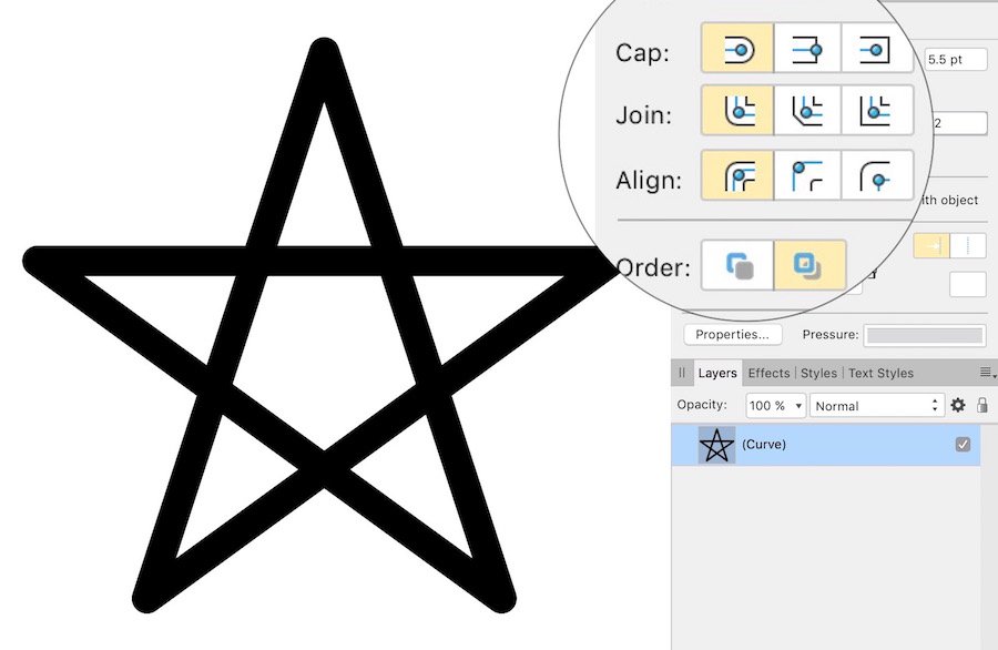
Note the join options. If you want a sharp corner, change to mitre join, and adjust the miter limit as needed.
-
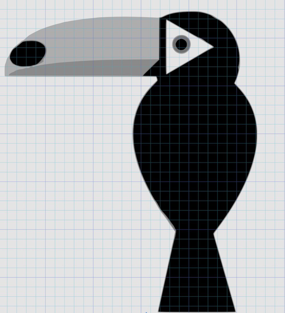
Affinty doesn't have a "shape builder" which allows selection of areas only defined by line perimeters. One can, however, dived the 2 expanded triangles, and add the resulting section together to create the same form. The improved pen snapping in v 1.7 makes simple line work like the above quick, and very accurate. It is slightly quicker than dividing and adding pieces.
-
Basic vector drawing, Designer
gdenby replied to gdenby's topic in Tutorials (Staff and Customer Created Tutorials)
Sorry, never ocurred to me that I could do that. -
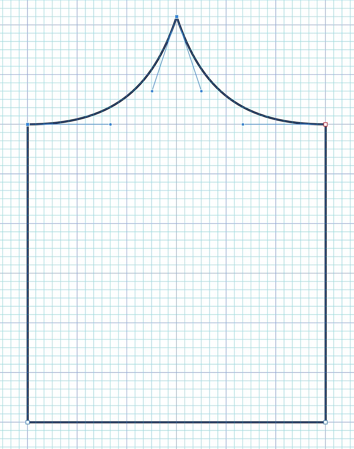
This is a response to a question by user SunRiseMoon on July 02. 2019. A quick basic drawing lesson. As of this writing, shapes in Affinity designer have 2 attributes, the stroke and fill. Those are defined by vector curve(s). To be filled, those curves can be either open or closed, as long as they surround a 2D area. But if they are open, any "boolean" operation, such as add or divide, will close the curves between the end point of each. This often produces unusable shapes. In Affinity, shapes ar made frome a series of nodes, each one connecting to only those adjacent in the series. The nodes cannot connect to more than 2 other nodes. There is no branching of a curve object. In order to get filled areas of color, if the shape is to be made from the curves that are already there, the curves must be selected, and thru the node tool, joined, and then closed. Sometimes one may need to duplicate existing curves, and cut out sections w. the node tool. These can then be used to create an area that meets shapes that are already there. *** In the owl face example, various strokes were given varying thicknesses by manipulating the pressure curve. Those were "expanded," and added together to form ink like strokes. 3 of the original vector strokes were closed, and so those pen lines could have a fill assigned to them, and for smooth continuous areas of color. Other lines were unclosed shapes positioned either above of below the closed shapes. When the shapes were filled, most were below in the layer hierarchy, and so were hidded by the fill. I selected the "beak" line. See the copies go thru these steps. The line is closed. The closing line is extended upwards for a more natural appearance. A fill is assigned, and the stroke set to "none." the unclosed curve is then matched to the filled curves position, and given a varying line weight. At a reduced size, the beak group was placed over the face. OwlHeadStart.afdesign
-
Hello, again. I'm placing a small explanation and demonstration about this in the tutorials section.
-
Hello, SunRiseMoon, I hope the translator works for this: My guess is that the lines were made from pen strokes. The strokes had their pressure curves modified to make tapers and swells. Then the pen strokes were "expanded, and added together. Expanding strokes can make shapes w. huge numbers of nodes, but I've found that if the strokes start rather simples, and are smooth, the final curve shape can have not too many nodes. Here is the file. For the fun of doing it, I colored the lines. The fills can be in-painted however on likes. OwlHead.afdesign
-
From the screen grabs, it looks like the letters are individual objects, and I'd expect to be able to select each or all, and, using the fill pop-out, assign color of gradient. The wall, however is just a collection of lines. Affinity doesn't work like a paint program. To fill an area, it must have a surrounding vector. You might try selecting the outer boundary of the wall, and join the curves w. the node tool. Then that can have a fill, and the brick lines and letters can be on a layer above.
-
affinity designer Multiverses - artwork on affinity designer
gdenby replied to padura's topic in Share your work
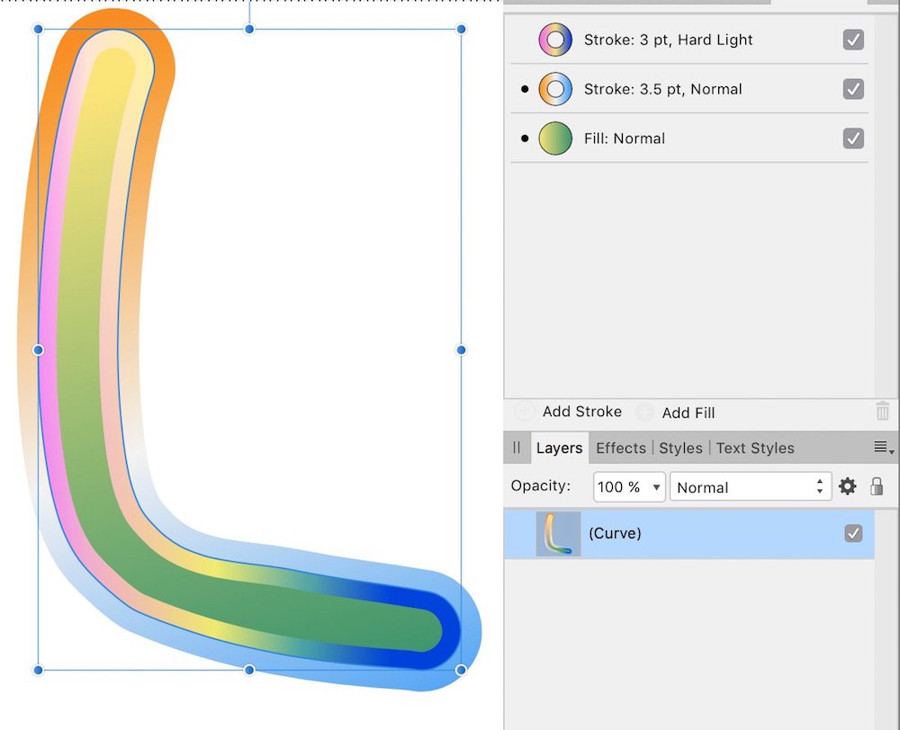
New in 1.7, the ability to add multiple strokes and fills to a single curve w/o expanding stroke, or duplicating objects to layer fills one on another.
-
affinity designer Multiverses - artwork on affinity designer
gdenby replied to padura's topic in Share your work
Very nice. Looks like you are using the new appearance studio to good effect. -
affinity designer Some last work, icons.
gdenby replied to Andrew Khodchenko's topic in Share your work
Wow, very nice! -
Fade letters
gdenby replied to MikeT40's topic in Pre-V2 Archive of Affinity on Desktop Questions (macOS and Windows)
Hi, MikeT40, Some years back, I was doing grave research, and had the same issue. W. A-Photo, there are a number of easy ways. I used the selection brush and gave the selection a feather of 2. I then used the filter "Noise/dust and scratches, w. a low setting. That is visible in the left of the top line. To the right, I reselected the "dusted" area, and applied "Noise/Diffuse," value 1, followed by Gaussian blur, .5 On the bottom, I just ran the blur brush across the "dusted" area. When I was doing this, it was as research for monument styles across the years, so I wanted to retain a sense of the surface. Gaussian worked OK, not good, but better than "Average.'
-
Designer: Cut tool
gdenby replied to mnh's topic in Pre-V2 Archive of Affinity on Desktop Questions (macOS and Windows)
No scissors yet. Use booleans the subtract, add, intersect, etc. -
It would probl'y be good to feed a screen cap of the logo thru GIMP to desaturate the image. Use the "average" method for desaturation. Here's a shot of what I got as an .svg: Obviously needs a good bit of work. Like @firstdefence, I'd likely just work it up manually. The image is quite simple, many primitives, and a few simple curve shapes.
-
Hi, s uɐɟəʇs, I'm certainly not privy to Serif's decisions. But what I infer from using both is that Designer and Photo are at core made for very different tasks. Photo is aimed at RAW development, and subsequent bitmap adjustment and compositing. Designer is for vector illustration w. an emphasis on layout and isometric drawing. In the case of Designer, the fx are there to round out the text and shape vectors as common practice have used them for years. For myself, the cost of both is small enough that buying both is not problematic, The fact that I can switch back and forth between the apps w/o converting the file type is a plus.
-
affinity designer Packaging Design - Marmalade with Honey
gdenby replied to Aurelio's topic in Share your work
A delicious looking design to go with the product! -
"None, no gradient anymore." Same here, can't find a way to set a gradient point to "none" that doesn't wipe out all the coloring.
-
Select the group from which you don't want to select any object. Hide the group. That is, uncheck the group in the layer panel. After that, you can only select on screen what is visible.