mllindsey
-
Posts
5 -
Joined
-
Last visited
-
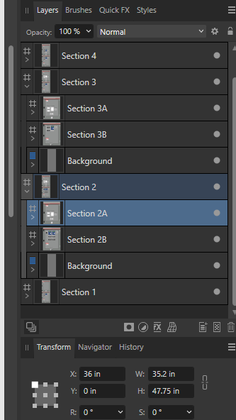
I appreciate your help with this. It does look like I can do a lot of what I was wanting with creating slices, didn't really understand the power behind that part. For example, I can change my faceplate artboard to a faceplate 'layer' and it looks like I can create a slice of that. It generates what I need that way. It looks like artboards are already defined as slices which is why I never paid attention to the layers tab on there. As for printing, we have export settings saved for the different types of outputs we need. For the labels, our printing company wants our export (pdf in this case) to have certain settings. The machine shop that laser cuts the doors needs a different output format. So when I am exporting faceplate files, I go to the export persona, select the artboard(s) to export and assign them to the saved correct export format. That's the reason that placement has to be consistent, so the faceplate has the same hole sizes as the laser cut doors and everything lines up. As for nesting, the artboards are inside the parent artboard on the layers tab. Not sure if there is another setting, or a different way to create those that I'm missing. In this screen shot, Section 2A is a top door. I thought it was nested under Section 2, but it's placement is relative to the 'origin' artboard (Section 1 in this case). I was expecting it to be relative to Section 2. So Section 2A is positioned at X:36" (which is the width of each section, so relative to the 0,0 of Section 1) and I would expect it to be X:0 (where Section 2 is positioned at X:36").

-
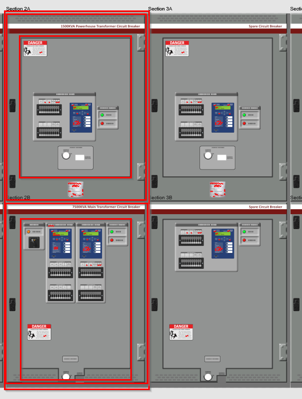
I'll admit I'm probably using artboards in a way most people aren't. I use Designer to create faceplate labels for large electrical equipment. The first task is I create a 'rendering' of the equipment that is used to allow the customer to visualize the entire lineup of equipment. The file I create has the rendering, the door cut pattern, and the faceplate label all in one file. I use artboards because I can ensure that equipment is placed in the same position on each section. In this example picture, each red box is an artboard. There is a section artboard so I can place each section correctly on the overall file (the number of sections changes per project). Each door (upper and lower) is an artboard and holds the door cut pattern. That's used to have the doors laser cut for device mounting. Then each door has a faceplate artboard. That contains the label, the devices, and the cut patterns for the label. That gets exported and sent to the printer. What I'm trying to accomplish is not having to create a separate drawing/file for each step of the process. Currently, I create the rendering file (what's shown). Then copy the faceplates to a separate file to get them to print properly. Then copy the door cut files to another file for printing. I'm using the export persona to do the exporting because I can bulk export doing that. I haven't found a way to export groups of layers into files that way. For example, the faceplate has a label layer, a device layer, and a device cutout layer. When I export the faceplate to send to the printer, the label layer and the cutout layer are visible. When I do these exports I can be exporting anywhere from 1 to 20 faceplates. When I export a png for display, the label layer and the device layer are visible. If I could position the door artboards in relation to the section and the faceplate artboards in relation to the door, I can ensure that the devices in the doors are in the same position across the lineup. That also would allow me to copy an entire faceplate from one door to another (see the top doors in the attached picture) and know they are positioned the same. That's a long winded explanation, but hopefully that makes sense.
-
When placing objects (vector, bitmap, etc) on a artboard, the position is relative to the artboard boundary. For example, if I have artboard 1 placed at position 0,0 and I place a rectangle at position 0,0, it will be placed in the upper left corner of the artboard 1. If I have artboard 2 placed at position 12,12 and I place a rectangle at position 0,0, it will be placed at the upper left corner of artboard 2. When I nest artboards, the nested artboard position is relative to the entire document. In the example above, if I place a nested artboard in artboard 2, and place it at position 0,0, it will show up on top of artboard 1, not in the upper left corner of artboard 2 like the rectangle in the example. It seems that when I nest an artboard into another artboard, the position reference should be the same as if it were an object (relative to the parent artboard boundary).
-
When using the Cog Tool, the Curvature red handle only works when zoomed in on the shape. This happens whether Snapping is enabled or not. The context menu works correctly regardless of zoom level.
-
When exporting a file as PDF, I can reliably cause Affinity to crash. With the document open: Select Export from the File menu Select the PDF tab Preset: Select PDF (for web) Raster DPI: Select 300 (or anything above 72) (this causes the 'Preset' to go blank) Select the 'More' button Enter '150' in the 'Downsample images' 'Above DPI' Select the 'Close' button Affinity will crash as soon as you hit the 'Close' button. "An Unhandled Exception has occurred. Code: 0xE0434352"