Greyfox
-
Posts
312 -
Joined
-
Last visited
Everything posted by Greyfox
-
 @Visin See If you can see the Camera model and Lens model in the line near the top of the screen, and the lens model can be selected manually from the pull down list, then the two issues may be related.
 -
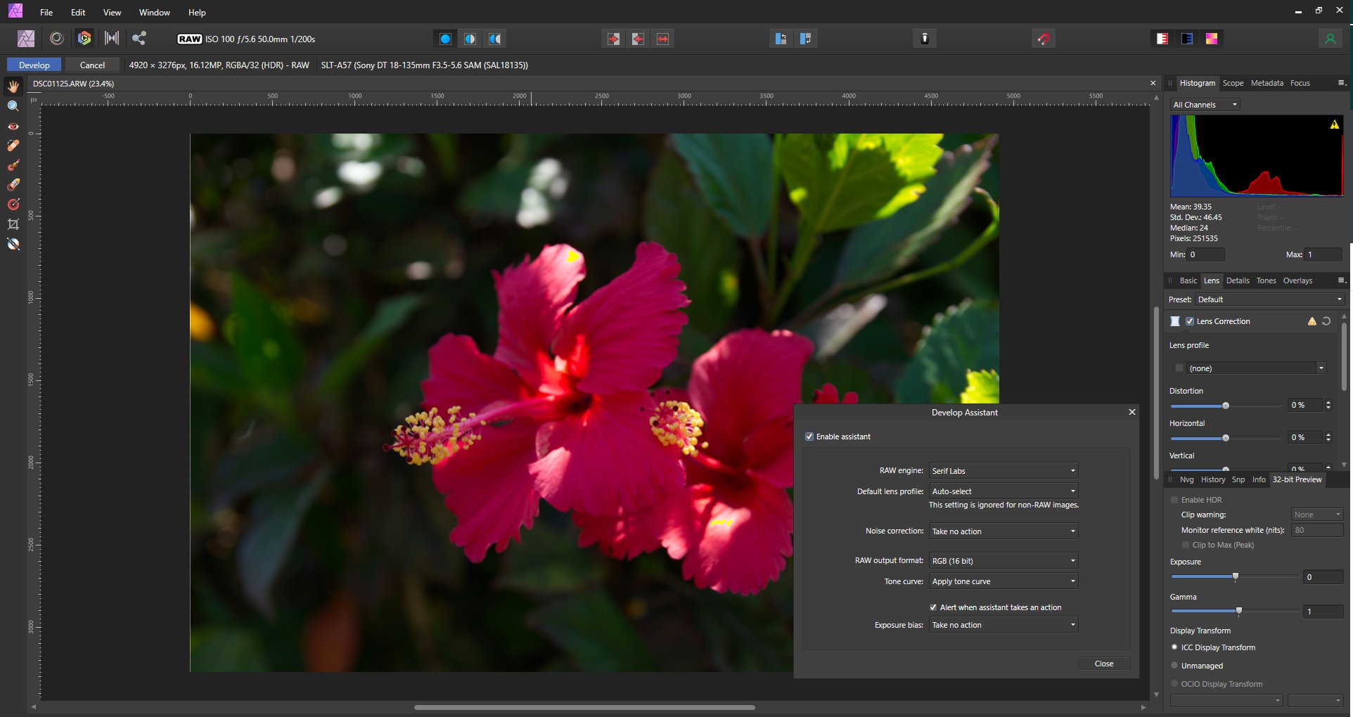
I thought I would raise the question here in case it is something I'm doing, or not doing that is causing the issue, rather than it being a bug in the software. When I open a RAW file in the Develop Persona, it is not automatically selecting the lens profile, even though (a) Develop lens profile is set to Auto-select in Develop Assistant (b) the camera and lens model are correctly identified in the line near the top of the screen (just to the right of the Cancel button) (c) the exact lens model can be manually located in the pull down profile listing The screen shot below shows the issue for a Sony .ARW raw file, and it is not just one individual image, but all I have tried from that particular camera. It is also occurring with RAW images from Canon as well. Any thoughts please. Edit: Affinity Photo 1.9.2.1035

-
See also the conversations at
-
@prophet, @Pšenda My experience is that touching one slider in a layer effect isn't enough to have the whole layer effect applied to the selected objects. 1. Draw two circles the same diameter, say 100mm. (or draw one and make a copy). Fill color one red and one yellow. 2. Select the red one, open the layer effects panel, select 3D, then change Radius to 100px and Specular to 100% 3. Leaving the layer effects panel open, now select both the red and yellow circles. Note at this stage no effect has been applied to the yellow circle. 4. Change the 3D radius from 100px back to 90px, then back up to 100px. Note that the 3D effect has been applied to the yellow circle. 5. Deselect both circles, then individually select them and check the two 3D slider values. What I'm finding is that whilst the radius is 100px on both, the specular on the red is 100%, and on the yellow its 50%. It seems to me I would have to touch every individual slider that had been changed from its default setting, or am I missing something?
-
OK, I understand. If the Scale with object box is not ticked, you are saying the size of the effect should remain unchanged (not be scaled) when the size of the object is changed, and I agree with that. And indeed, if the box is left un-ticked, then if the original box is resized, the effect does stay at the original size, but if it is copied to another object the size is changing.
-
Strange. I used the Transform box to size both rectangles and In my case it was exactly 25px and then scaled back up to exactly 50px.
-
Sorry, I don't understand that. The original effect was 50px relative to a 100mm object, with the scale with object ticked. When it pasted into the second rectangle, the size of the object had reduced by half (to 50mm), and the effect was scaled down by half (to 25px) When the object was then resized to 100mm (doubled), the effect also doubled (back to 50px). I don't see that as uncontrolled.
-
My results are different, perhaps because of an extra item 1. Create a 100mm x 100mm rectangle, and fill with solid color 2. Create a 50mm x 50mm rectangle and fill with a different solid color 3. Select the 100mm x 100mm rectangle and apply a Gaussian Blur layer effect set to 50px 4. Important - in the Layer Effects dialog, tick the "Scale with Object" box near the bottom left hand corner. 5. Copy the larger rectangle and then select the smaller rectangle and apply "Edit->Paste FX" Now when I examine the layer effect for the smaller rectangle, the Gaussian Blur is 25%. 6. Use the Transform panel to increase the size of the small rectangle from 50mm x 50mm to 100mm x 100mm. Now when I examine the layer effect for that rectangle, the Gaussian Blue if 50%. That is doing what I would expect, it is scaling the layer effect with the object size.
-
You haven't said which Affinity product but In Publisher that can be done in the Print dialog. If you are working with individual pages, in the Pages field you would enter 12,21 and under layout set Double-sided to Flip long side, and model to Single. That would print page 12 on one side of the paper, and page 21 on the other If you are working with a folded booklet form, then set the model to Booklet and the Double Sided to Flip short side . Assuming a 24 page document, then with the pages set to 12,21 as previously, it would print pages 4 and 21 on one side of the sheet, and 12 and 13 on the other side, and for a 32 page document it would print page 12 and 21 on the same side of the sheet.
-
1. Type text - for the example I used Arial font 150pt, color 225,10,225 2. Duplicate the text layer 3. Select the lower of the two text layers and in the context tool bar click on convert to Curves 4. With that layer still selected, In the (Text Group) context toolbar, set the stroke to 65 pt, and the color to 52,255,255. That produces the cyan'ish first level background. 5. Now select the upper text layer and add the black letter outline. There are several ways this can be done. With the text selected, in the context toolbar set the stroke color to Black, the stroke width to around 10pt and the order to "draw Stroke behind". Alternatively with the text layer selected,at the bottom of the layer panel click on the fx (layer effects) icon. In that layer effects dialog select Outline. Leave Blend as Normal, Opacity as 100%, set Radius at around 22px. Leave Alignment as outside, Fill style as Solid color and Color as black. 6. Add the background yellow rectangle. You can either use the rectangle tool, or the rectangular marquee tool and Flood fill on a new pixel layer. Either way put this layer at the bottom of the layer stack. 7. To replace the dot on the letter "i" with a star, you first need to cover the dot with a small rectangle set to the same color as in step 4. Again you can do that with either the rectangle tool, or the rectangular marquee tool and flood fill on a new pixel layer.Put that layer above the upper text layer. 8. Use the star tool to produce the "starred dot" for the letter "i" and put that layer at the top of the stack. I'm not sure what you mean about missing an outline on the white part. There was no white part in your sample image. The white part in the file I posted was the page background. This would either be white or transparent depending on how you set your page up. Normally with a logo, I would expect you would select just the area of the logo itself, and in the export dialog set the area to "selection only", but if you do want a white area outside of the yellow then try this. If your page is white, go to the Document menu and click on Transparent background. That will change the background to transparent. Now use the rectangle tool to drag out a rectangle of the size you want, set its fill and stroke colors to white and place that layer at the bottom of the stack.
-
Maybe like this Logo.afphoto
-
Thank you. That put me on the right track. I had tried that without success before posting, along with a bunch of other keys, however what I've now found is that it has to be the LEFT Alt key whilst dragging the node. Holding down the RIGHT Alt Key doesn't work Although I'm in Australia, my Windows 10 Pro is set to English United States, and using a US keyboard. I don't know whether that makes any difference.
-
In the above screen shot, the pressure curve has three points, with the one on the left higher than the one on the right. When I attempt to duplicate that, if I move the one on the right down, the one on the left moves down. How are you able to move them independently?.
-
6032 x 4032px 24.32MP D750 .NEF Raw files opening in Affinity v1.9.2.1035 here OK. What operating system? Can you provide a link to one of the images you can't open?
-
I think maybe this is the same issue that was raised here: And as far as I can see, it is still an issue in 1.9.2.1035 For now, my work around is to press the "a" key to change to the node tool, then "p" to change back to the pen tool.
-
For those that still have it installed Serif's DrawplusX8 had a spiral tool.
-
+1
-
In my case whilst the rectangular marquee selection is present the CPU use by Affinity is a mere 1.9%, and that drops to 0% when I click on Deselect. I assume that providing the marching ants when selected accounts for the small CPU usage.
-
Yes that works too, thanks for the suggestion. 😀
-
Thanks Alfred, I was aware of the node method to obtain an open arc of quadrant, but it was actually a closed quadrant I needed and your suggestion of using the Pie Tool works for me. 😀
-
Nice as Affinity Designer is, after years of working with DrawPlus, I'm finding it hard to make the change to the newer Affinity product. Today a simple task, to change an old bitmap logo to a vector based one. Right from the outset, I couldn't find a b-spline tool . Spent some time on line searching, and it seems some of the coding for it has been in the product for a few years, but it has never been activated. Each year people have asked about when a b-spline tool would be available, but as far as I can see, there has never been a positive commitment. So here in 2021, I'll ask the question again "when can we expect a b-spline tool?" I spent some time with the pen tool smart mode, but the amount of re-work necessary to get decent curves was just way too daunting. Next issue, I couldn't find an arc tool. What I needed was a simple quadrant. Was able to produce one by drawing a circle, then subtracting two rectangles to cut off the unwanted bits. Surely there must be a less clunky way? In the end it was taking too much time so I took the easy way out and went back and did the job in DrawPlus X8.
-
Sorry, I'm a Windows user, so I can't help you. Hopefully one of the Mac users can.
-
What OS and which Affinity App? Is the Save As screen in each case by chance "under" the Affinity Screen?
-
You can resize an artboard at any stage, or you can add additional artboards as required. So if you make the initial artboard large enough to include all of the items in the original Inkscape file, and you then want to add something new outside of that area, either expand the artboard or add an additional artboard. I doubt the size of an artboard would have any significant effect on performance, however the nature and amount of the content added to an artboard might have, as it might on an ordinary page. I haven't experienced any problems with this myself.
-
Carol, maybe this. If I export to PDF from Affinity Designer using the PDF (press ready) preset, and then in my PDF viewer (PDF-XChange Editor) set the preferences to show Bleed, it shows the bleed lines. To get a faux border line, on the Master page, use the rectangle tool to drag out a rectangle to the border lines. Set the fill to none and the stroke light blue 1.0pt. That will give you a faux border line that matches the real one on all the pages subject to that master, which will also appear in the PDF. If the faux border is placed on a separate layer on the master page, un-ticking that layer will remove it from all of the pages. In the attached screen shot of an A4 facing page document, the faux 15mm border is shown in blue, and the 5mm bleed appears in green. Perhaps one snag with the above is if the PDF reader used doesn't have the option of showing the bleed lines.