bpedit
-
Posts
208 -
Joined
-
Last visited
Everything posted by bpedit
-
Curious whether there's a way to lock an object, such that it doesn't scale for example, but still allow for it to be translated. [One of my Designer uses is for stained glass work. Once I've designed the pieces, all fitting together precisely, I need to move them around individually to fit on stencils or pattern assemblies to print out while maintaining their shapes and sizes. I often see that I've changed the proportions instead of grabbing the object to drag for translation and then have to hope I haven't missed undoing any of these errors.]
-
How about some spacers to separate items (layers and groups) in the Layers panel. Maybe two choices: 1/2 normal height of an item and 1/4 height. These would be devoid of symbols and text and could be dragged and dropped like other items. I frequently create dummy items to separate clusters of items in the Layers panel allowing for faster parsing. But the dummy items take up a full height and don't parse as quickly as they could due to the identifying icon on the left. (I'm mostly working on an iPad Pro.)
-
Paul's response reminded me I should have included my device specs, a 3rd gen. 12.9" iPad Pro.
-
Evidently I'm using 96 dpi, I had to search to find this. I think I set it long ago such that SVG exports were compatible with CNC . I just tried resetting the DPI to 192 (96 x 2) and I get the same idiosyncracy. Edit: Paul's response below reminded me I should have included my device specs, a 3rd gen. 12.9" iPad Pro.
-
Working in Designer on iPad (in millimeters), I find that the artwork, as measured on the screen with a ruler, is equal to the dimensions as measured by Designer when the Navigator is set to 50% for the scale of the artwork in the display. That is, if I create a square 50.0 mm on a side, it physically measures as such at 50% enlargement. This has been true since version 1. I've looked through the Settings but don't see where I might have enabled this behavior in some way. I'm curious. I can live with this but, not knowing the source, feel like I must constantly check when creating a new file lest it changes somehow.
-
 Oh, oh. The decimal precision display does not apply to the Stroke Width where I need it most! (I have posted this in bugs.)
 -
On iPad the new options for decimal places are not reflected in the Width display of the Stroke panel, nor in the Width adjustment panel (but do appear in the Stroke icon).

-
Yea! All other modifications henceforth are pure gravy!
-
Is it possible to delete a post before anyone has responded?
-
How about letting us double-click on an item in the Adjustment list to directly open the dialog for adjusting? (Versus having to click to open the preset panel, then having to move to and click on the "(default)" button.)
-
One-click Adjustment dialog opening?
bpedit replied to bpedit's topic in Affinity on Desktop Questions (macOS and Windows)
Thanks! The adjustment I use the most, Levels, is Command-L, how simple. I'll look to see if I can shortcut Exposure and Brightness/Contrast as well. -
When you select a parameter in the Adjustment panel it doesn't directly open the dialog for adjusting. Instead you're presented with various presets one of which you then have click on to open the dialog. Is there a way to immediately open the dialog without this extra step? (I'm looking at something like 10,000 needless mouse clicks during my slides-to-digital editing!)
-
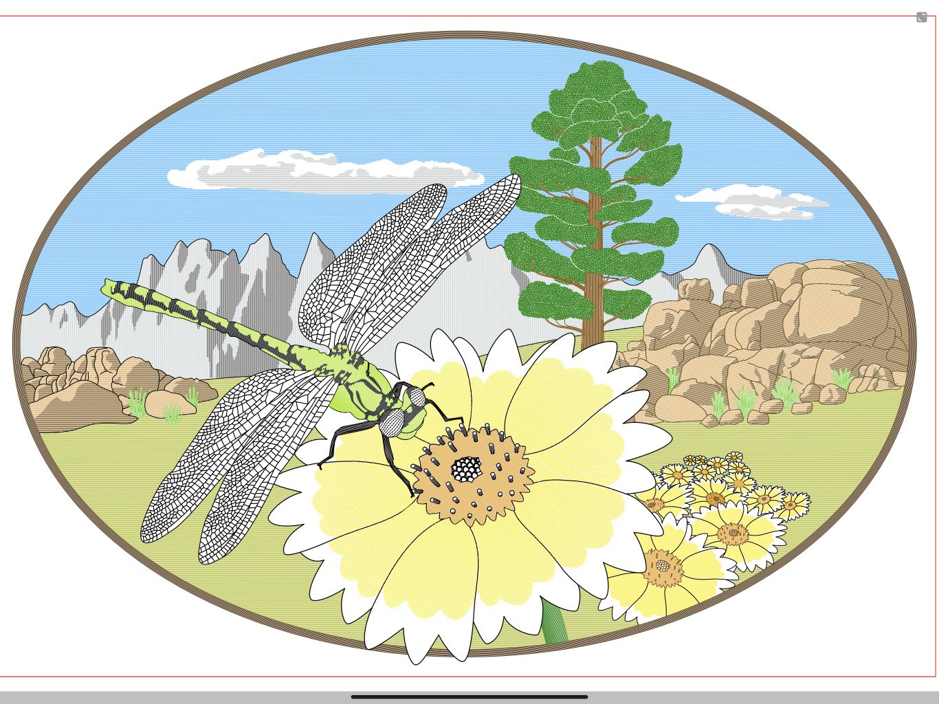
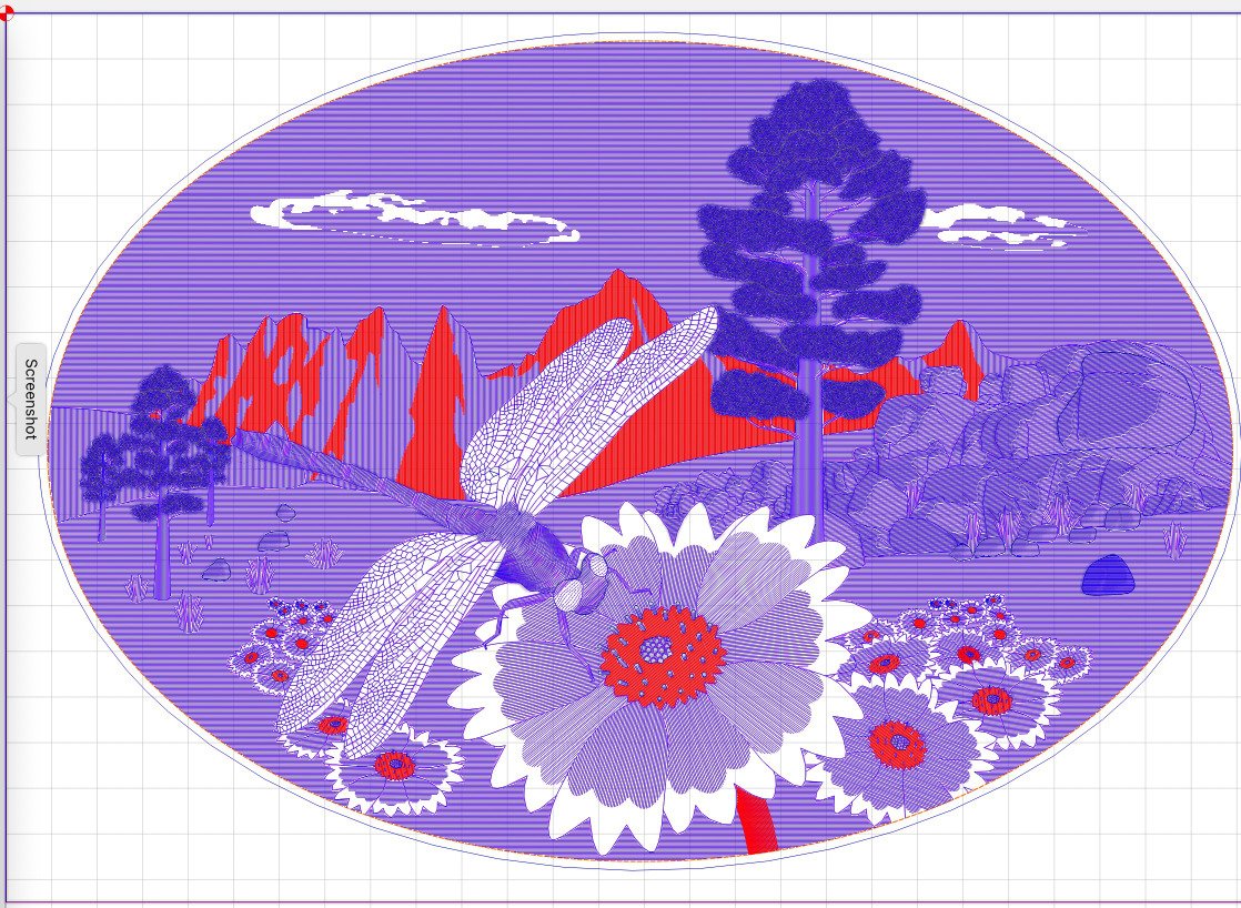
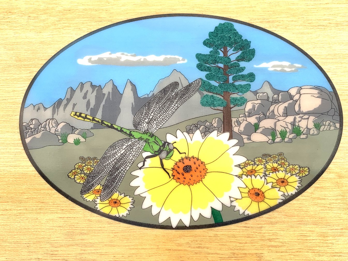
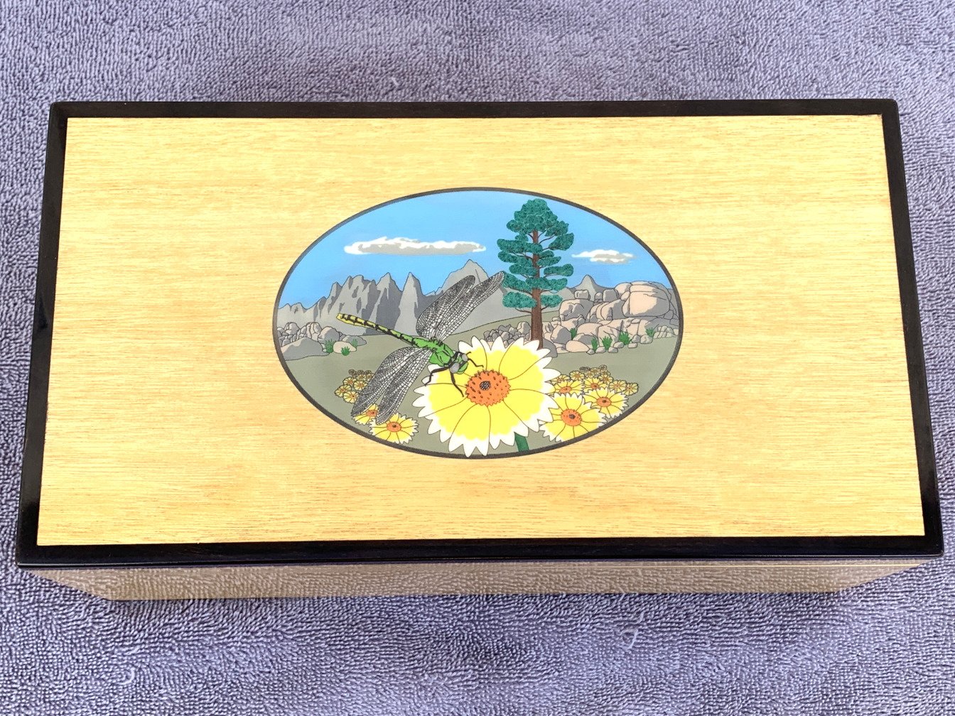
This is the first project using a process I'm developing for colored engraving, on a Nomad CNC machine, of faux ivory substrates, for inlay into jewelry boxes. The process needs more improvement but I was happy enough with the results to begin a second piece. It begins with the creation of the artwork in Designer. The actual oval is smaller than show, at least on my screen, about 130 mm wide. The lines to be engraved are 0.15 mm apart. Here is the graphic depiction of the lines to be engraved by the machine. The red color represents one pass out of a total of seven necessary to keep the colors separate. The final product inset into the box. The box itself, a gift to my niece. She wanted a "tree" and "daisies" although I gave her Tidytips instead.
-
Thanks. I will have to go that route. My initial test with the multi-point lines was positive but I can't repeat it. I'm thinking it has something to do with the frequency of the Mesh nodes compared to the frequency of the line nodes. I need to export to SVG anyway for use in the CNC mill so I'll just leave the Mesh unconverted. The result of this method isn't exact, in my analysis, but likely close enough. Now for some testing on the machine. Thanks again. Edit: The exported SVG of the unconverted Mesh is very close, maybe exact, to the appearance of the Mesh before Converting to Curves. This would seem a good hint as to how to remedy the issue.
-
Thanks, disappointed to hear. I'm not sure if this file is the exact same as pictured above, I've gone through a few iterations. I tried it on desktop as well, maybe should have posted there. waterTst.afdesign One work around I can think of is to introduce nodes in the lines before applying the Warp. There appears to be no way to do that in AD except point-by-point. Maybe I'll try recreating the grid by duplicating a single line with the multiple points already extant. Edit: When I remade my grid based on a line with multiple midpoints then applied the Mesh I got satisfactory results. Thanks for helping me realize I needed a work-around versus something I was doing wrong.
-
After further testing I infer this has to do with AD deciding it can accommodate some of the induced curves by adjusting handles on existing points versus inserting new points. When the mesh is converted to curves the new points are respected but the adjusted handles are not. Could a moderator please move this over to bugs.
-
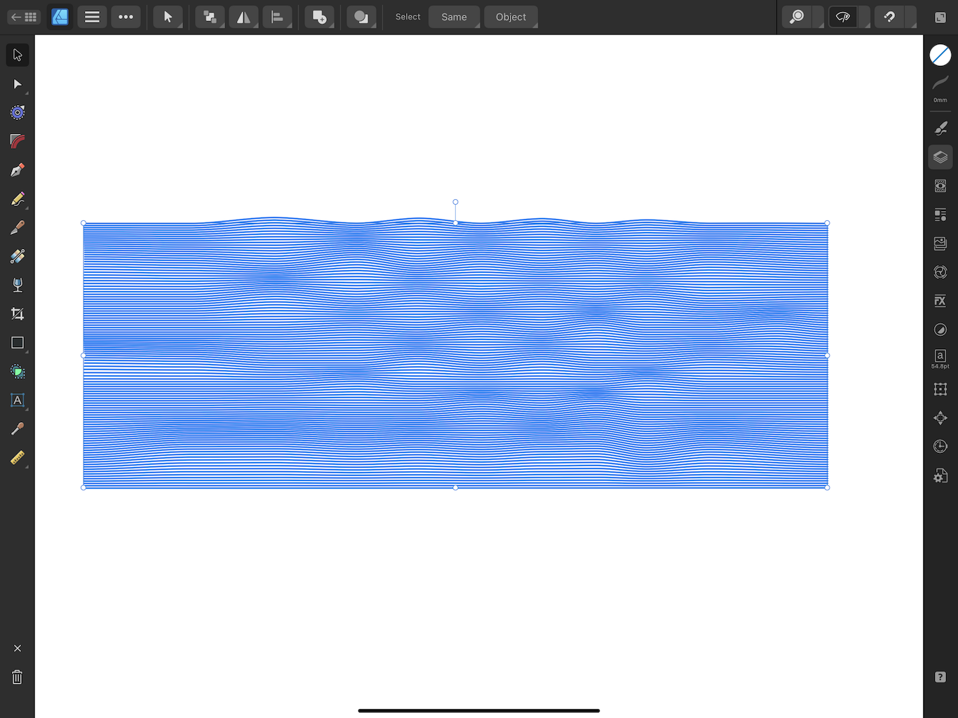
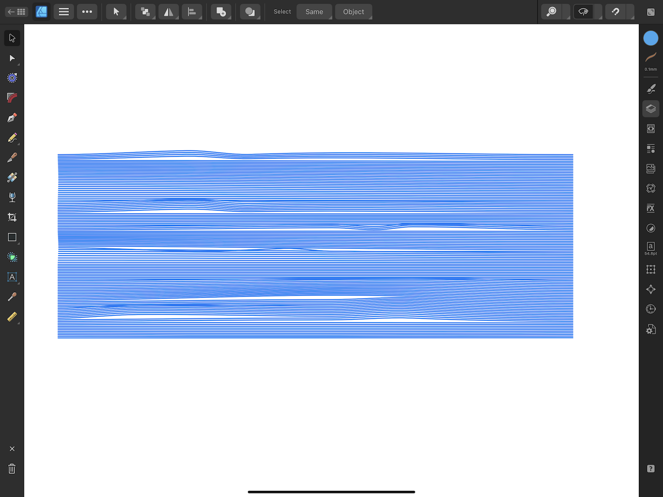
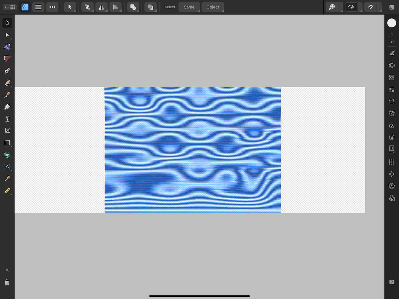
Here's the mesh I'm using on a bunch of parallel lines, attempting to simulate water for an engraving project: When I exit Point mode I get this, looking good for my first trial anyway: But when I Convert to Curves, I get this: Ooooh, ick! What's going on? Strangely, if I Export the object, with the unconverted mesh intact, as an SVG, the results are closer to the desired result but not quite as desired.
-
It's useless to me because I don't use it, simple as that. If I need it there is another place to find it. I'm stumped as to why this would be associated with point manipulations, at least in such a way that one would constantly need to access it. This is on iPad, mind you, where I would much prefer the added screen space. Why do you think it appears there, in this redundant manner, when it is accessible with the Pen or Pencil Tool? In what way is this a valuable asset for other modes of use?
-
Whenever I activate the Node tool a Line size slider appears on the left of the screen uselessly taking up real estate. How do I get rid of this?
-
Decimal-place accuracy missing still
bpedit replied to johnnydfred's topic in Feedback for the Affinity V2 Suite of Products
I absolutely concur, I need more decimal places in the display for line size and object position especially. Ideally this precision will be adjustable in preferences as done in the desktop version. I understand the real estate challenge of implementing it on iPad but I'm sure the clever folks at Serif can solve that. For example, use rectangles instead of space wasting circles. Currently I often have to re-enter a size for a given object just to verify that it's as expected in order to fit a new element. All my current work, for CNC use, needs 0.01 mm accuracy. -
Move and not Save? Why?
bpedit replied to Affinity-Inspiration's topic in Affinity on iPad Questions
To me this is a no brainer. The use of Move implies that the file has been saved. To be considered saved implies that the user can subsequently access it at will, not that it be in the background of an active app and subject to the disposition of the app. The use of "move" is typically applied to a transfer to another folder within a particular app for a file that has already been saved. -
Save JPEG at original quality
bpedit replied to bpedit's topic in Affinity on Desktop Questions (macOS and Windows)
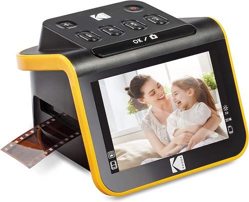
I used a Kodak scanner, a SLIDE N SCAN, it reviewed a bit better than the Kodak you pictured. It's fast at snapping the pic, the time is mostly in giving the slides a blast of air and feeding them into the scanner. The quality was mostly pretty good, some batches ("trips") not as good but that appeared, after examination with a scope, mostly a matter of the quality of the original. If you just have a few to do a professional job would probably be better, they pay more attention to cleaning and have better scanners, too expensive for a one-off use. This was adequate for my use. Remember to keep an eye out for specks lodging on the platen and use the included brush to remove them.
-
Save JPEG at original quality
bpedit replied to bpedit's topic in Affinity on Desktop Questions (macOS and Windows)
The scanner offers no choice but JPEG. -
Save JPEG at original quality
bpedit replied to bpedit's topic in Affinity on Desktop Questions (macOS and Windows)
Interesting. Would this be the same, quality wise, as saving from the original opened file at the new resolution? I may test this. Walt: I can't tell the difference between saving at 100% and saving at 95%, even at magnification. I would challenge others to point out the difference. Remember, I'm not working with high resolution digital originals but images of 35 mm slides taken with a 12 Mp scanner. The memory savings for my collection would be on the order of 25 GB. -
Save JPEG at original quality
bpedit replied to bpedit's topic in Affinity on Desktop Questions (macOS and Windows)
The edits will very depending on the image. Dust removal, white point adjustment, contrast, dozens more possibilities unique to each photo. Color correction for wash-outs from the 1960's. While I understand the philosophy of keeping the "original" archived, with 3600 photos I won't be saving to new files and doing the comparisons you suggest. These are scanned to begin with, some uneditable editing was done then. This is a 'get it done' operation, its why I was looking to save 10,000 keystrokes and 7,000 mouse moves. I guess my original question should have been a simple "can you adjust the JPEG quality as applied to the save button when a flattened JPEG is active". The answer appears to be no.