jalamb
-
Posts
11 -
Joined
-
Last visited
Everything posted by jalamb
-
View Single Layer
jalamb replied to coranda's topic in Pre-V2 Archive of Affinity on Desktop Questions (macOS and Windows)
You will have flattened the layers, probably with ⌘ + E to Merge Down. You will need to go back through your history to go back to before you did that. -
View Single Layer
jalamb replied to coranda's topic in Pre-V2 Archive of Affinity on Desktop Questions (macOS and Windows)
"I thought I tried it and it didn't do anything." This only works if you are changing layer with the alt-click - If you have layer 3 selected and alt-click on layer 3, then nothing happens, but if you alt-click on layer 2 then only layer 2 is displayed. So to display only layer 3 you would have to click on another layer first, then alt-click back onto on layer 3. Affinity Photo 1.7.3.481 -
Thank you both. That makes sense. Very helpful information.
-
Hello, I have an ORF file from my Olympus EM1 camera which Lightroom, Olympus Viewer 3, the exif and Windows all show to be 4608 x 3456 pixels, but when I open it in Affinity it shows as 4640 x 3472 (and similarly any pixel file I create from it.) Have I got a setting wrong somewhere or is something going on that I am not understanding (or should I be posting this under bugs?)
-
Yes, it’s the right screenshot. It already has the curve applied, so the white has changed to 87% cyan. Thanks, Dan C, I didn’t realise that thread was there.
-
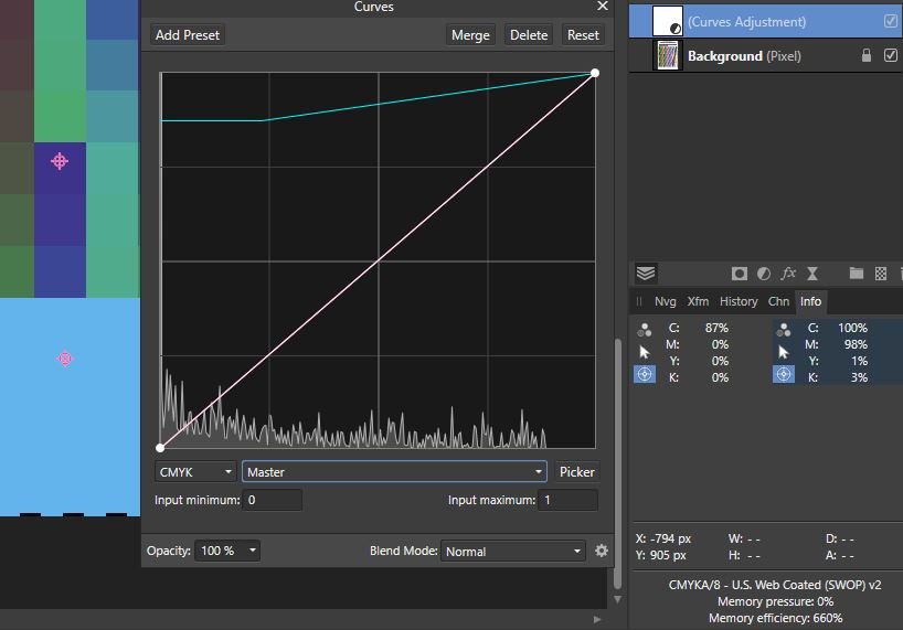
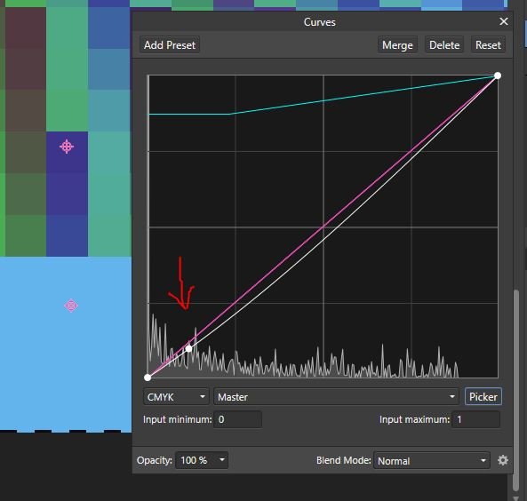
Bug: The pickers do not pick the correct point in the Curves dialogue The graphs in the Affinity Curves dialogues input at the bottom and output at the left Input (bottom) has zero left and 100 right Output (left) has zero bottom and 100 top This can be seen in the following: On a CMYK version of a colour chart I have set two Samplers on the Info panel - the left sampler in the white paper, showing 0,0,0,0; and the right sampler in the pure cyan square showing 100,98,1,3 The curve in diagram 1 shows: a huge spike on the left at zero, from the white of the paper zero transformed to 87 (from the flat of the line on the left 100 being unchanged by the point top right of the graph These are confirmed by the new sampler values, the blue tinge to the white paper, and the unchanged solid cyan square If I now use the picker and place it in the cyan square, the node created on the graph is bottom left, somewhere around (12,12) in coordinates (second screenshot). First it should clearly be at one end of the line (as the blue square is 100% cyan) and it should be at the right-hand end of the line. Similarly if I reset and use the picker to choose from the white area (with zero cyan) it gives me a node top-right, rather than bottom left. This error can go unnoticed when selecting a single node because the curve will be symmetrical, so, if, say, the point chosen was 80, then the node would be 20, and the resulting curve when dragged down would be down equally at 80 and 20. However when trying to create an S curve, it falls apart (and wastes a lot of time!) Software version: Affinity Photo 1.7.0.367, Win 10 Home version 1803 OS build 17134.829, 64bit, Intel Core i7-7700HQ installed RAM 16Gb

-
Need Precision Curves Adjustment
jalamb replied to martinch's topic in Feedback for Affinity Photo V1 on Desktop
I also want precision curve writing as I do corrections in LAB to take specific point (highlights, shadow, etc.) to specific values for certain papers. Using the picker doesn’t seem to work for the second point on the curve, but numeric input would be much easier even if the picker did work. -
Of course not. There is not a set amount of ink which has to be used and if you reduce the amount of blue then more red ink will be used! But as I said previously, that does not happen with a CYMK document, only with an RGB or LAB document. So what is going on is that using a CMYK curve on a RGB document involves converting the image to CMYK, doing the curve, and changing it back. Clearly it is the conversion which is introducing the changes in the other channels. This is not something which Photoshop includes and now perhaps we see why.
-
No. In CMYK Cyan Magenta Yellow are primaries so do not affect each other. Just the same as in RGB changing the amount of Red does not impact Blue.
-
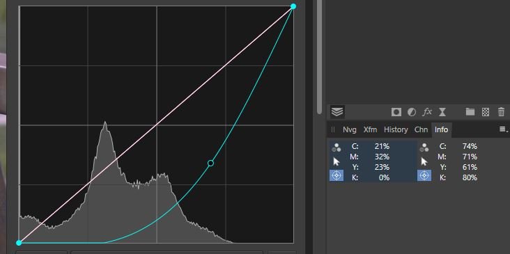
Ah, got it.... It only works properly if the file is actually in CMYK. The file I was using was actually in LAB, and then I tried with a file in RGB. The result was the same, with the screen shots below: moving just the Cyan channel, the Magenta value changes from 70 to 71. With the Magenta channel everything moves! If I convert the file to CMYK first, rather than just selecting CYMK in the Curves panel, then it does work. So that is better than not working at all. Thank you for the help.
-
Hello, I am trying to do some colour corrections using curves in CMYK but don't understand what is happening (or possibly Affinity is not working correctly). I have a colour image and I open the Info Panel and add two samplers, both of which I set to CMYK. I then add a Curves layer, and select CMYK. If I choose the Black channel, and move the curve around, the values in ALL the channels in the samplers change, not just the K values. Similarly, moving the Cyan channel curve makes changes to ALL the channels. What I am trying to do is to change a value of c74 m69 y64 k83 to become c80 m70 y70 k70, but I can't see how to do this. I realise that I can't put numeric values in the Curve (as in Photoshop) but even using the picker and dragging seems completely unpredictable.