CreativeTim
-
Posts
10 -
Joined
-
Last visited
-
Rounded corners appear as squared corners
CreativeTim replied to CreativeTim's topic in V2 Bugs found on Windows
Apologies for my late reply, I was preoccupied with school the past couple of weeks. I just started with this project, so there's not much to show unfortunately. I am also still figuring out how detailed I want my map to be. The main reason for the artifact that I mentioned becoming an issue is that I intend to have the large area map and local detailed sections in the same artboard, so that I can easily switch between the two. I want my large area map to look somewhat similar to what you can find on Google Maps for example. And the detailed local sections I want to make look more like aerial photography, where for example road markings are also visible (though I'm not an artist so it will look more like an urban design plan). One of the uses for the detailed map is to see whether the proportions look right (i.e. if the sizes of buildings make sense). Considering I use a scale of 1 km = 100 pt (1 m = 0.1 pt) and the aforementioned artifact occurs when two nodes are less than 0.12 pt apart, a road median with rounded corners of anything less than 2.4 m in width would therefore not work. Perhaps AD is not the right tool for my project, but nothing offers quite the same level of creative freedom as that of a vector graphics editor like AD. At least not that I know of. -
Rounded corners appear as squared corners
CreativeTim replied to CreativeTim's topic in V2 Bugs found on Windows
I came across this artifact while making a map (as in cartography). The added benefit of making it very detailed is that I can decide later which portion I want to turn into a wallpaper for my desktop, whether that'll be a city or a single street. Perhaps for most people this artifact wouldn't be much of an issue, but for me this artifact is very visible. -
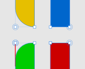
I am using the latest version of Affinity Designer (2.2.0) on my Windows 10 desktop PC. Nodes changed with the Corner Tool display weird behavior when the distance between the nodes is 0.12 pt or smaller. This strangely only occurs in nodes that are on the right side of an object. I am able to consistently reproduce the artifact with new objects and in new documents. To demonstrate the issue I have created 4 squares of 2x2 pt with the Rectangle Tool. For each square I changed a different corner to rounded with a corner radius of 1 pt: File: Corner Tool Artifact.afdesign I then reduced the width of each object to 0.119 pt. For the blue and red objects, the corners remain rounded but simply reduce in size, as expected. For the yellow and green objects, the corners become squared when the distance between the node manipulated with the Corner Tool, and another node becomes less than 0.12 pt (which translates to 0.5 pixels). Note that the corner type is not set to None by AD, it remains Rounded, but does not appear as such in the document. To further show that it only occurs on nodes on the right of the object I horizontally flipped each object individually. As you can see the objects that had their rounded corners on the right now have them on the left and vice versa, but the rounded corners on the right side of the objects appear as squared corners: Things that I have tried that result in the same artifact of rounded corners appearing as a squared corners: Disabling hardware acceleration. Recreate the object in the same document and in a new document. Horizontally or vertically flipping the object. Rotating the object 180 degrees. If an object has rounded corners on the left side and is rotated 180 degrees, the rounded corners are now the right side. The corners still appear rounded after rotating, but the artifact reoccurs after resizing the object or dragging any node in the object. Likely other manipulations will also make the artifact reoccur, but I haven't tried. Undoing any actions will not make the corners round again (when the rounded corners are still on the right side of the object). Rotating the object 180 degrees and leaving it as is, is not a workaround. After saving and reopening the document the artifact reoccurs. Increasing and decreasing the corner radius.

-
 CreativeTim reacted to a post in a topic:
Nodes move when adding small objects
CreativeTim reacted to a post in a topic:
Nodes move when adding small objects
-
CreativeTim reacted to a post in a topic:
Feature request for the layers panel - reverse order of selection
-
I am using the latest version of Affinity Designer (2.2.0) on my Windows 10 desktop PC. When adding multiple very small objects together the combined shape is sometimes not the same as the combination of objects before adding. In other words, if I were to make a copy of the group of objects I want to combine, after adding the copied objects together, the new combined object does not overlay perfectly with the original group of objects: Depicted above: objects before combining in grey (left) and new combined object in red (right). File: Add-Artifact Test.afdesign. Upon adding the objects AD seems to create new average nodes between the objects resulting in a distortion of the shape (I can provide more images with explanations if that is necessary). I tried to reproduce the artifact with different but similarly sized objects and was able to reproduce the artifact for some of the objects. I have not been able to figure out why it happens in some cases and not in others: The smallest distance between two nodes in any of the objects that I am trying to add together is 0.004 pt. I tried disabling hardware acceleration, but did not produce a different result.
-
CreativeTim reacted to a post in a topic:
Adding (perfect) circle shape, radius invariant to rotation.
-
CreativeTim reacted to a post in a topic:
Adding (perfect) circle shape, radius invariant to rotation.
-
 CreativeTim reacted to a post in a topic:
Mirror text on path
CreativeTim reacted to a post in a topic:
Mirror text on path
-
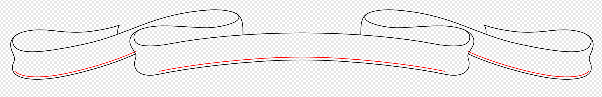
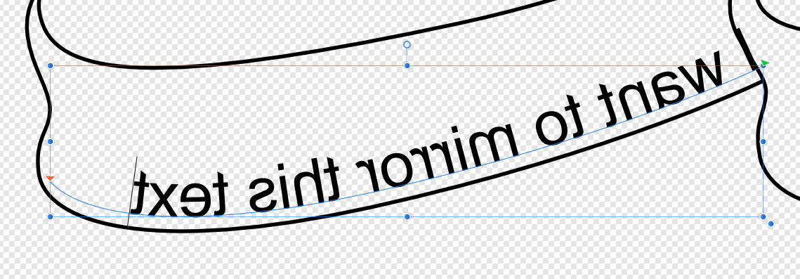
I'm having an issue with putting text on a curved path in the motto part of my coat of arms that I'm trying to make. I first made the right side, mirrored it, and then connected both sides to ensure that it is perfectly symmetrical. Now I want to add text to the red curves, but since the red curve on the left is a mirrored version of the one on the right the text will be mirrored as well, as you can see in the image below. So my question is, how do I mirror text along a curved path?
-
CreativeTim reacted to a post in a topic:
Issue with snapping multiple points of an object
-
R C-R reacted to a post in a topic:
Issue with snapping multiple points of an object
-
CreativeTim reacted to a post in a topic:
Issue with snapping multiple points of an object
-
CreativeTim reacted to a post in a topic:
Issue with snapping multiple points of an object
-
CreativeTim reacted to a post in a topic:
Issue with snapping multiple points of an object
-
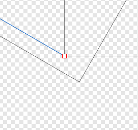
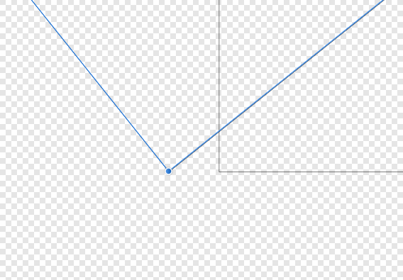
I appreciate you all taking the time to help me. I found Aammppaa's solution to work best. The corners align perfectly. As for R C-R's I can see how you managed to do it (thanks for the "History"-tab tip), but the corners don't perfectly align. I tried to replicate it to see if it was accidentally shifted, but it seems that it's a bug in the software itself (I think). As you can see the selected line was my initial line I made with the Pen Tool (I am zoomed in a ridiculous amount by the way). Also used the Butt Cap as you mentioned. Besides, Aammppaa, can you tell me how managed to make such a nice gif? Looks a lot better and easier to understand than the tons of images I used. Old Bruco, no worries, and thank you for trying to help me out. (One more question: I noticed how you can use @[name] to address to a specific person, is it okay to use in general posts on this forum or is that too direct? I have no idea, I'm totally new to this, so that's why I'm asking.)
-
The dimensions of the fixed rectangle are: W: 400 pt - H: 490 pt. The width of the rectangle should be 110 pt. XZYTE.afdesign
-
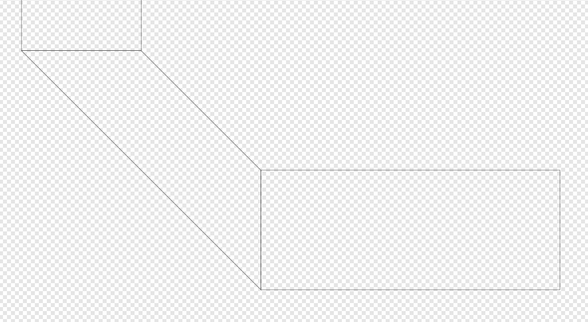
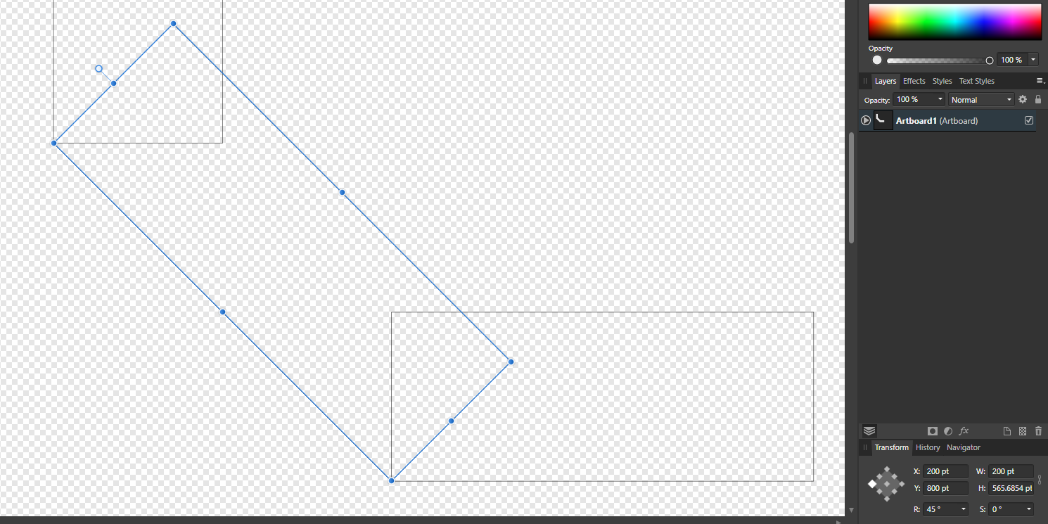
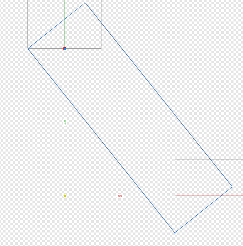
I think my explanation isn't fully clear. Imagine this: I have two rectangles with the same width perpendicular to each other with a gap in the place where they will meet each other. In this case the width of both rectangles are 200 points. I want to connect those two rectangles by putting another rectangle in between them, I can do it the way in the image below. The problem here is, I want that diagonal rectangle to be the same width as the other two: 200 points, which it is clearly not. In the image below I've added another rectangle, rotated by 45 degrees. The height doesn't matter as long as the selected rectangle has a width of 200 points and snaps to the corners of both the other rectangles. The reason why it works here and not in the image I posted earlier is that in this case the distance between the rectangles and the point at which their centers would intersect is the same (therefore I can easily use an angle of 45 degrees to make the corners snap). In a case where their distance to the point at which their centers intersect is not the same, I can calculate the angle of the 3rd rectangle... ...but because the angle here is a fractal number (in this case: 36.8698989...) it will never perfectly align. So I wondered if there's another way to do this. (Sorry for all the pictures, but I want to make my point clear. Hope it is now.)
-
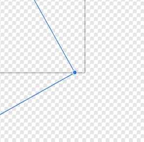
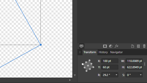
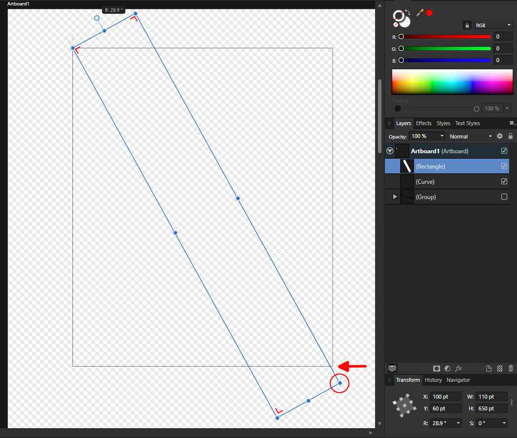
The grey one should stay as is. The one that is selected should keep its width of 110 points, its height doesn't matter. The issue is, when I rotate it from the origin point on the top left I have to eyeball the right border of my selection to intersect with the corner of the black rectangle, which means they will never perfectly intersect. And when I start dragging that circled point its width is also getting changed. When rotating the corners don't perfectly intersect. Width changes when dragging the corner.
-
I've recently bought Affinity Designer, so I'm not really familiar with all of its tools and features yet. I'm trying to make a logo for myself, but I ran into a problem. What I'm trying to achieve is to get the circled corner of my selection to snap the the bottom right corner of the black outlined rectangle while the width of my selection stays 110 points and the corners are all 90 degrees. Basically, what I want is to lock the width of my selection at 110 points and grab the circled corner, rotate the selection from its origin point and have its height automatically adjusted when I make it snap to the the corner of the other rectangle. (I see I didn't had the "Enable Transform Origin" visible when I made the screenshot. It's where the corners of both the selection and the other rectangle meet in the upper left corner.) I hope the issue I'm having here is clear.